Quick Introduction
3 Quick Introduction
3.1 Requirements
– HAMEGHM8118LCRmeasuringbridgewithrmwarefrom
1.37 upwards.
– HZ184 Kelvin measurement cables
– 1 x HAMEG 1,000 µF capacitor (not contained in shipment)
– 1 x HAMEG 280 µH inductor (not contained in shipment)
– 1xHAMEG100kΩresistor(notcontainedinshipment).
First connect the HZ184 cables supplied to the HM8118. The
two plugs of the black cable are connected to the terminals
LCUR and LPOT, the plugs of the red cable to the terminals
HCUR and HPOT.
Afterturningtheinstrumenton,therststepsaretheopen
circuit and the short circuit calibration procedures at the pre-
selected frequency of 1.0 kHz because the measurement cables
HZ184, in conjunction with the terminals, due to their design,
show a stray capacity, a residual inductance and a residual
resistance which impair the accuracy of the measurement re-
sults.Inordertominimizetheseinfluences,thecompensation
of impedance measurement errors caused by adapters and
cables is necessary.
For the open circuit calibration, position the two clips apart
from each other. For the short circuit calibration connect both
clips as shown in Fig. 3.1.
Fig. 3.1: Short circuit calibration with HZ184.
Push the button MENU/SELECT
3
and then the button C-D
34
in order to enter the CORR menu. Select the menu item MODE
and use the knob
5
to change the menu entry from SGL to
ALL in order to automatically perform the calibration at all
69 frequency steps provided. Leave the menu by pushing the
button MENU/ESC
5
.
Hint:
The mode SGL is used to only calibrate at the pre-
sently selected frequency; this procedure takes just
a few seconds and is destined for measurements in
one or a few frequency ranges only.
Now start the open and short circuit calibrations by pushing the
buttons ZERO/OPEN
11
resp. ZERO/SHORT
12
. The instrument
will now determine correction factors at all 69 frequency steps
valid for the presently connected measurement cables and store
them until the instrument is switched off. This procedure will
last appr. 2 minutes.
3.2 Measurement of a capacitor
Now connect the capacitor to the terminals of the HZ184.
Please observe the polarity of the capacitor and connect the
black terminal to the negative terminal of the capacitor, marked
with a – (minus).
As the instrument is set to automatic mode, the measurement
function will be automatically switched to function no. 3 (C-D).
Because the measuring frequency of 1.0 kHz was preselected,
the capacitor will not be measured in its regular operating
mode, so the value displayed of appr. 900 µF will not equal the
speciedvalueof1,000µF.
Change the measuring frequency to 50 Hz by pushing the button
SET/FREQ
8
and turning the knob until 50 Hz are shown on the
display. Now the value displayed will change to appr.1,000 µF
depending on its tolerance. The dissipation factor „D“ will be
very low at this setting.
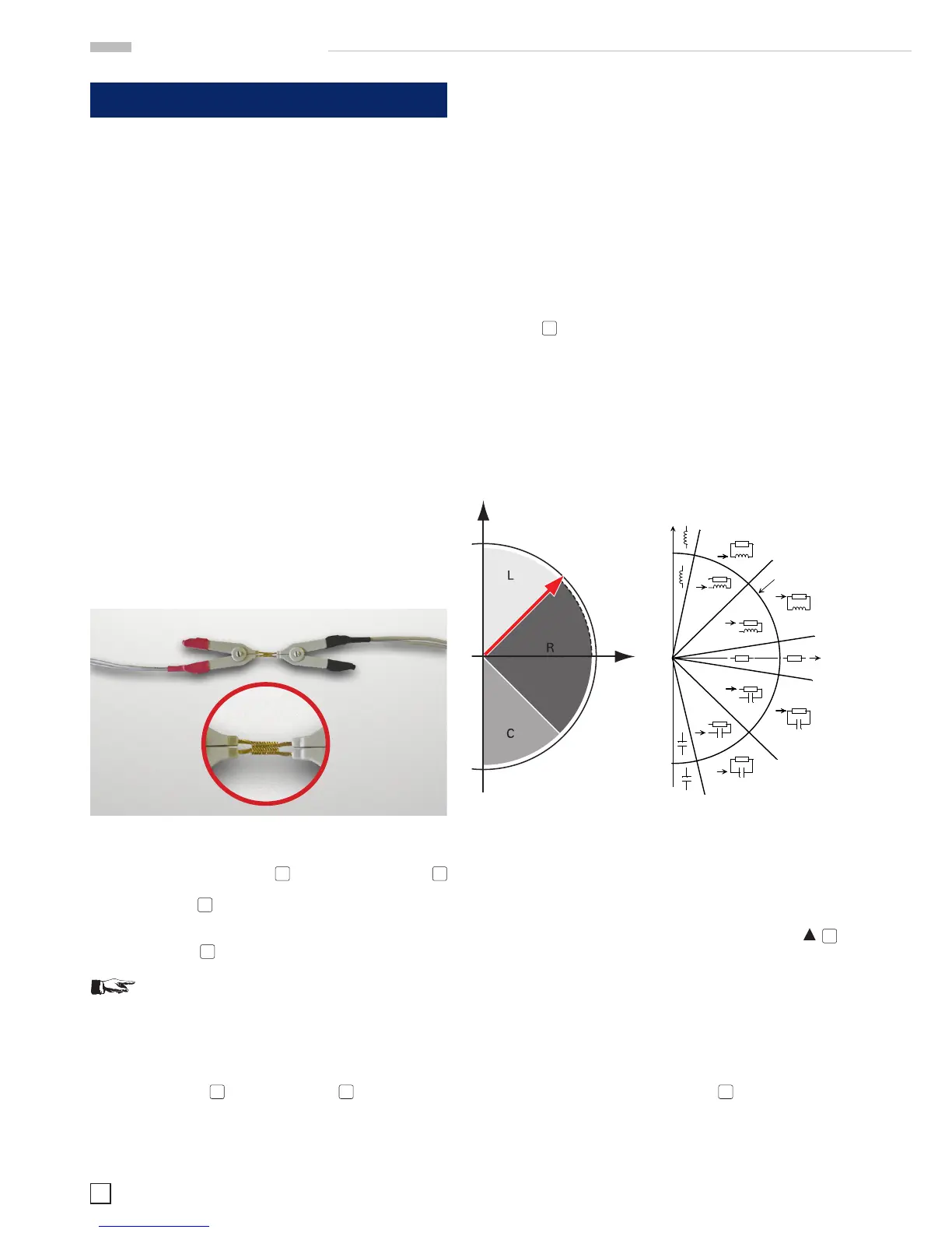
The smaller the loss angle, the more the real world components
will come close to the ideal. An ideal inductor has a loss angle
of zero degrees. An ideal capacitor also has a loss angle of zero
degrees. An ideal electrical resistor, however, has a loss angle
of 90 degrees, it has no capacitive or inductive components.
Fig. 3.2: HM8118 measurement principle, left: schematic, right:
detailled presentation.
3.3 Measurement of an inductor
Before you connect the choke, increase the measuring frequen-
cy by one decade to 500 Hz by pushing the arrow button
7
above the knob. Disconnect the capacitor and connect the choke
to the terminals of the HZ184.
The instrument will now automatically switch to the function
no. 1 (L-Q) and the inductance of the choke will be displayed.
The value should be appr. 280 µH.
As shown in Fig. 3.2, the phase angle of an inductor must be in
the range of + 45 to 90°. In order to prove this, leave the auto-
matic mode by pushing the button „Z-
Θ
39
. The phase angle
displayed will be appr. + 70° and depends on the measuring
frequency set.
For comparison: the phase angle of the capacitor measured
before is appr. - 87° at 50 Hz.
applied on the red terminal. The bias voltage works only
when the instrument on capacitance measurement
mode.
Measuring function selection
The desired test function is selected by push buttons (12)
and (14). The push button (12) gives access to the main
parameter (R, L or C), The push button (14) allows a
secondary parameter measurement (Q/D, impedance or
phase).
In order to measure D parameter the instrument needs at
first to be set to capacitance measurement mode, on the
other way, Q parameter will be displayed.
Auto-measurement function
The HM8018-2 is able to automatically determine the
component type in most cases. 3 different automatisms
exists: the automatic impedance range selection (see the
section « Auto-ranging»), the automatic mode
(series/parallel) selection (see the section « passive
components »), and the automatic function selection. These
three automatisms are simultaneously activated when the
instrument is set in automatic mode with the RANGE
AUTO key (7). Then the user can change function or mode
that disables their respective automatism. The manual range
selection disables the three automatisms.
When the instrument is on automatic mode the function
choice depends on the impedance module, phase angle as
well as the quality factor .The diagram below shows the
choice made by the instrument.
Calculation functions
Apart from displaying normal values as resistance, inductance or
capacitance, the HM8018-2 can display relative deviations and
percentages. It is not possible to use these calculation modes for
other functions than the three previous values. The deviations
and percentages are displayed in relation to the two stored values
A and B.
The procedure to obtain relative measurement is as follows:
1) Connect the component corresponding to the reference
value.
2) Store the value (memory A) by pressing on the STORE key,
then press the A key.
3) Press on the A key. The indicator -A lights up and the
display shows the value (Measure – A).
A direct percentage measurement is possible, it is only to use the
÷B key instead of the –A key in the previous procedure. Then the
instrument displays the value 100*Measure/B in %.
To obtain a deviation in % proceed as follows:
1) Connect the component corresponding to the reference
value.
 Loading...


