Connecting of components andmeasurement accessories
7.2 Kelvin measurement cable HZ184
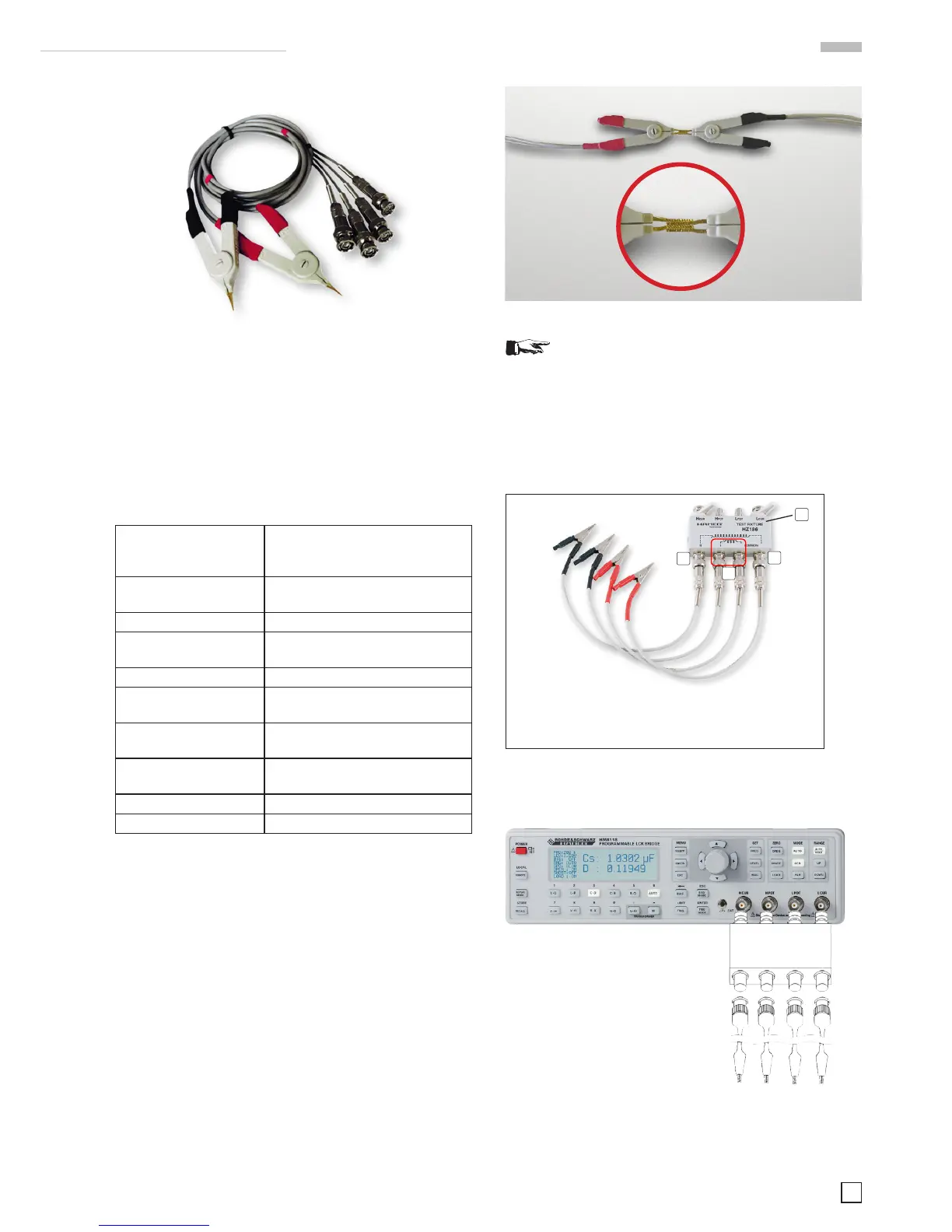
Fig. 7.3: Kelvin measurement cable HZ184
The Kelvin measurement cabel with Kelvin clamps enables the
measuring of components which are too big to measure with
conventional test adapters. The measuring cable is connected
directly with the 4 BNC plugs on the frontpanel of the LCR
bridge HM8118. The red clamp cables are being connected
to H CUR and H POT, the black clamp cables to L POT and L
CUR. This accessory is contained in shipment.
7.2.1 Specications
Function: Kelvin measurement cable set
for operation with the LCR bridge
HM8118 (4-wire connection)
Measurable compon-
ents:
Resistors, coils, capacitors
Frequency range: 20Hz...200kHz
Measurement cable
length:
About 35cm
Connections: BNC plug (4), test clamps (2)
Safety standards EN61010-1; IEC61010-1;
EN61010-031; IEC61010-031;
Environmental condi-
tions:
Degree of pollution 2, intended
for indoor use
Operating tempera-
ture:
+5 °C ... +40 °C
Storage temperature: –20 °C … +70 °C
Weight: about 170g
7.2.2 Calibration
The measurement cable set HZ184 in conjunction with the
clamps, due to its construction, has a stray capacity, a residual
inductance and a residual resistance which impair the accuracy
ofthevaluesobtained.Inordertominimizetheseinfluencesitis
necessary to compensate for impedance measurement errors
caused by the adapter and the leads.
To compensate for or to eliminate these measurement errors,
an OPEN and a SHORT calibration should be performed at the
LCR bridge HM8118. The procedure is explained in chapter 5
„Calibration“. The calibration values obtained during the cali-
bration will be stored in the LCR bridge HM8118 and remain
valid until the next calibration.
For an OPEN calibration both connectors must be arranged
disconnected. For a SHORT calibration both connectors must
be connected to each other (see Fig. 7.4).
Fig. 7.4: Short circuit calibration HZ184
With frequency dependent components it is important
that an OPEN and a SHORT calibration is performed
for each of the 69 test frequencies.
7.3 4 wire transformer measurement cable HZ186
The measurement adapter HZ186 is destined for the mea-
surement of transformers in conjunction with the transformer
functions of the LCR bridge HM8118.
Änderungen vorbehalten
Produktbeschreibung
Der Messadapter HZ16 ist zur Messung von Transforma-
toren bzw. Übertragern in Verbindung mit den Transforma-
tor-Messfunktionen der LCR-Messbrücke HM11 konstru-
iert. Der Messadapter wird direkt über die vier BNC-Stecker
an die frontseitigen BNC-Buchsen der LCR-Messbrücke an-
geschlossen. Zur besseren Bedienung der Messbrücke soll-
ten die Betätigungshebel der vier BNC-Stecker nach unten
zeigen.
Dieser Messadapter ist ein bequemes Hilfsmittel für die
Messung der Gegeninduktivität (M), des Übersetzungsver-
hältnisses (N) und des Phasenverschiebungswinkes im
Frequenzbereich von 20 Hz bis zu 200 kHz eines Transfor-
mators bzw. Übertragers. Der Messadapter dient hierzu als
Schnittstelle zwischen der LCR-Messbrücke und den vier bei-
liegenden Messleitungen. Zum Messen wird der zu messende
Transformator / Übertrager einfach auf der Primärseite und
der Sekundärseite über die Messleitungen mit dem Mess-
adapter verbunden.
Fig. 7.5: 4 wire transformer measurement cable
The measurement adapter is connected directly with the BNC
jacks on the front panel of the LCR bridge.
N 1 COMMON
red black
This measurement adapter is a comfortable means for the
measurement of the mutual inductance (M), the turns ratio (N),
and the phase angle (
φ
) of a transformer in the frequency range
1 Transformer Test Adapter
2 Test Cable for a high number of turns
3 Test Cable for a small number of turns
Fig. 7.6: Connection of the
measurement adapter to the LCR
bridge
 Loading...


