Subject to change without notice
First-time operation
Measurement Source Impedance of the
range Impedance component
1 25.0Ω 10.0µΩ — 3.0Ω
2 25.0Ω
3.0Ω —100.0Ω
3 400.0Ω
100.0Ω — 1.6kΩ
4 6.4kΩ
1.6kΩ — 25.0kΩ
5 100.0kΩ
25.0kΩ — 2.0MΩ
6 100.0kΩ
2.0MΩ —100.0MΩ
As the impedance of capacitors is inversely proportional to fre-
quency larger capacitances are measured in the lower impedance
ranges. Hence the proper range may change if the frequency
changes.
In case that several similar components have to be measured
inturn, the measurementtime can be shortened,if the rst
component is measured with autoranging on. The button AUTO/
HOLD
17
should be pressed to change from automatic range
mode to manual range mode and hold it. The button AUTO/HOLD
will extinguish.
In order to prevent measurement errors due to false operation
and uncertainties, it is advisable to always use automatic range
selection. Manual range selection should preferably be used if
highest precision is desired. In order to uprange press UP
18
, in
order to downrange press DOWN
19
.
4.8 Switching the equivalent measurement
circuitry
If automatic selection of measurement circuitry is enabled
(by pressing the AUTO
14
button) the HM8118 automatically
selects the resp. equivalent circuit (serial or parallel), which
provides the most precise measurement depending on the
connected component (ref. also to chap. 4.7). The measure-
ment circuit can also be selected manually (by pressing the
SER button
15
for serial mode or by pressing the PAR button
16
for parallel mode).
The SER/PAR mode represents the equivalent circuit of the mea-
suring circuit. Traditionally, the inductance of coils is measured
in a series circuit (serial); however there are cases where a
parallel circuit will yield a better representation of the compo-
nents. The core of coils with an iron or ferrite core for example
may contribute most of the losses. A series circuit should be
prefered if most of the losses are resistive, or they occur within
the connection wires of wired components.
In automatic mode the instrument selects the serial equivalent
circuitryforimpedancesbelow1kΩandtheparallelequivalent
circuitryforimpedancesabove1kΩ.
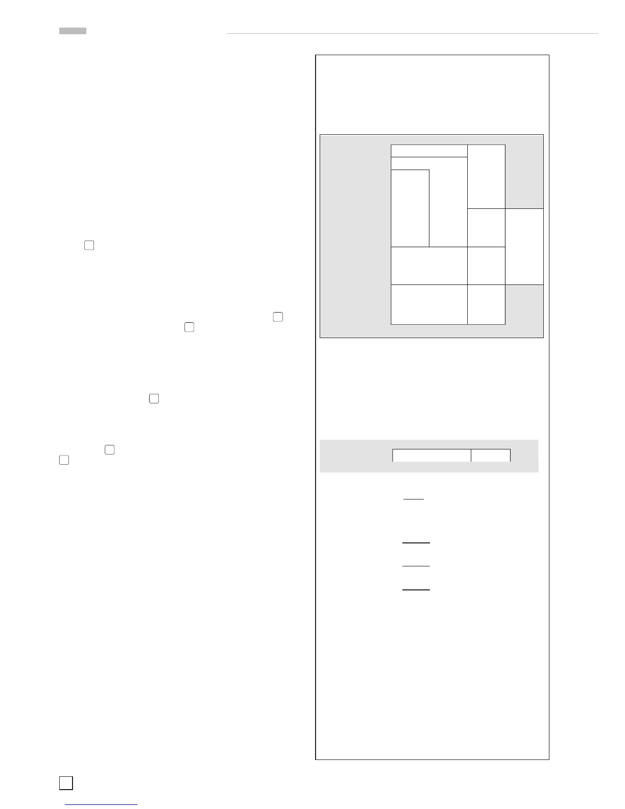
Example to determine the accuracy
of the HM8118
The accuracy calculation is based on the accuracy table of
the data sheet:
To calculate the appropriate accuracy, the following parame-
ters of the component are required:
– component impedance at the appropriate frequency
– the measurement frequency itself.
Measuring of a 10 pF capacitor with an impedance of
15 MΩ at 1 kHz
Inthiscase,therstlineoftheaccuracytableisvalid:
The values of the component set in into the formula:
15 MΩ
accuracy
@1kHz
= 0,2% +
1,5 GΩ
calculated / set in:
At last, the units need to be adapted, because the second
summand has no unit relation, yet:
accuracy
@1kHz
= 0,2% + 0,01 = 0,2 + (0,01 x 100%) = 0,2% + 1% = 1,2%
For the 10pF component this leads to:
1.2%of10pFis0.12pF.
Based on the calculation the displayed value will be between
10pF - 0.12pF = 9.88pF and 10pF + 0.12pF = 10.12pF.
HM8118E/160812 · C&E · Subject to change without notice · © HAMEG Instruments GmbH
®
· DQS-certified in accordance with DIN EN ISO 9001:2008, Reg.-No.: 071040 QM08
HAMEG Instruments GmbH · Industriestr. 6 · D-63533 Mainhausen · Tel +49 (0) 6182 8000 · Fax +49 (0) 6182 800100 · www.hameg.com · info@hameg.com
200 kHz LCR-Bridge HM8118
All data valid at 23 °C after 30 minutes warm-up.
Conditions
Test signal voltage:
1 V
Open and short corrections performed
Measurement time:
SLOW
Display
Measurement modes:
Auto, L-Q, L-R, C-D, C-R, R-Q, Z-Θ, Y-Θ,
R-X, G-B, N-Θ, M
Equivalent circuits:
Auto, Series or Parallel
Parameters displayed:
Value, Deviation or % Deviation
Averaging:
2…99 measurements
Accuracy
Primary Parameters:
Basic accuracy
(Test voltage: 1.0 V,
measurement SLOW/MEDIUM,
autoranging mode, constant voltage OFF,
bias off). For FAST mode double the basic
accuracy values
0.2% + |Z|/1.5GΩ
Impedance:
100MΩ
4MΩ
1MΩ
25kΩ
100Ω
2.5Ω
0.01mΩ
20Hz 1kHz 10 kHz100kHz
0.1% + 1mΩ/|Z|
0.3% + 1mΩ/|Z|
0.05% +
|Z|/2GΩ
0.1% +
|Z|/1,5GΩ
0.5% +
|Z|/100MΩ
0.2% +
|Z|/100MΩ
0.2% +
2mΩ/|Z|
0.5% +
5mΩ/|Z|
+
|Z|/10MΩ
0.5% +
2mΩ/|Z|
Secondary Parameters:
Basic accuracy D, Q: ±0.0001
@ f = 1 kHz
Phase angle: ±0.005°
@ f = 1 kHz
Ranges
|Z|, R, X:
0.01 mΩ…100 MΩ
|Y|, G, B:
10 nS…1,000 S
C:
0.01 pF…100 mF
L:
10 nH…100 kH
D:
0.0001…9.9999
Q:
0.1…9,999.9
Θ:
-180…+180°
∆:
-999.99…999.99 %
M:
1 µH…100 H
N:
0.95…500
Measurement conditions and functions
Test frequency:
20 Hz…200 kHz (69 steps)
Frequency accuracy:
±100 ppm
AC test signal level:
50 mV
rms
…1.5 V
rms
Resolution
10 mV
rms
Drive level accuracy:
±(5 % + 5 mV)
Internal Bias Voltage:
0…+5.00 V
dc
Resolution
10 mV
External Bias Voltage:
0…+40 V
dc
(fused 0.5 A)
Internal Bias Current:
0…+200 mA
Resolution
1 mA
Range Selection:
Auto and Hold
Trigger:
Continuous, manual or external via
interface, Binning Interface or Trigger
Input
Trigger delay time:
0…999 ms in 1 ms steps
Measurement time (f ≥1 kHz):
FAST
70 ms
MEDIUM
125 ms
SLOW
0.7 s
Other Instrument Functions
Test signal level monitor:
Voltage, current
Error Correction:
Open, Short, Load
Save/Recall:
9 instrument settings
Front-end Protection:
V
max
<
Z
X
2/C
@ V
max
<200 V, C in Farads
(1 Joule of stored energy)
Low Potential and
Low Current Guarding:
Ground, Driven Guard or Auto (fused)
Constant Voltage Mode (25 Ω source):
Temperature effects
R, L or C
±5 ppm/°C
Interface:
Dual-Interface USB/RS-232 (HO820),
IEEE-488 (GPIB) (optional)
Safety Class:
Safety Class I (EN61010-1)
Power supply:
110…230 V ±10 %, 50…60 Hz, CAT II
Power consumption:
approx. 20 W
Operating temperature:
+5…+40 °C
Storage temperature:
-20…+70 °C
Rel. humidity:
5…80 % (non condensing)
Dimensions (W x H x D):
285 x 75 x 365 mm
Weight:
approx. 4 kg
Accessories supplied: Line cord, Operating manual, HZ184 4 Terminal Kelvin
Test Cable and HZ188 4 Terminal SMD Component Test Fixture, CD
Recommended accessories:
HO118 Binning Interface
HO880 Interface IEEE-488 (GPIB), galvanically isolated
HZ13 Interface cable (USB) 1.8 m
HZ14 Interface cable (serial) 1:1
HZ33 Test cable 50 Ω, BNC/BNC, 0.5 m
HZ34 Test cable 50 Ω, BNC/BNC, 1.0 m
HZ42 19" Rackmount kit 2RU
HZ72 GPIB-Cable 2 m
HZ181 4 Terminal Test Fixture including Shorting Plate
HZ186 4 Terminal Transformer Test Cable
200 kHz LCR-Messbrücke HM8118
Alle Angaben bei 23 °C nach einer Aufwärmzeit von 30 Minuten.
Bedingungen
Testsignalspannung:
1 V
Leerlauf- und Kurzschlussabgleich durchgeführt
Messzeit:
SLOW
Anzeige
Messbare Kenngrößen:
Auto, L-Q, L-R, C-D, C-R, R-Q, Z-Θ, Y-Θ,
R-X, G-B, N-Θ, M
Schaltungsart:
Auto, Seriell oder Parallel
Angezeigte Parameter:
Wert, absolute Abweichung oder prozen-
tuale Abweichung %
Mittelwertbildung:
2…99 Messungen
Genauigkeit
Primärparameter:
Grundgenauigkeit (Testspannung: 1,0 V,
Messmodus SLOW/MEDIUM,
Messbereichsautomatik AUTO,
Konstantspannung OFF, Vorspannung
AUS). Für hohe Messgeschwindigkeit
FAST gelten die doppelten Werte der
0,2% + |Z|/1,5GΩ
Impedanz:
100MΩ
4MΩ
1MΩ
25kΩ
100Ω
2,5Ω
0,01mΩ
0,1% + 1mΩ/|Z|
0,3% + 1mΩ/|Z|
0,05% +
|Z|/2GΩ
0,1% +
|Z|/1,5GΩ
0,5% +
|Z|/100MΩ
0,2% +
|Z|/100MΩ
0,2% +
2mΩ/|Z|
0,5% +
5mΩ/|Z|
+
|Z|/10MΩ
0,5% +
2mΩ/|Z|
Sekundärparameter:
Grundgenauigkeit D, Q ±0,0001 bei f = 1 kHz
Phasenwinkel ±0,005° bei f = 1 kHz
Messbereiche
|Z|, R, X:
0,01 mΩ…100 MΩ
|Y|, G, B:
10 nS…1.000 S
C:
0,01 pF…100 mF
L:
10 nH…100 kH
D:
0,0001…9,9999
Q:
0,1…9.999,9
Θ:
-180…+180 °
∆:
-999,99…999,99 %
M:
1 µH…100 H
N:
0,95…500
Messparameter und -funktionen
Messfrequenzbereich:
20 Hz…200 kHz (69 Stufen)
Frequenzgenauigkeit:
±100 ppm
AC Testsignalpegel:
50 mV
Eff
…1,5 V
Eff
Auflösung
10 mV
Eff
Pegelgenauigkeit:
±(5 % + 5 mV)
Interne Biasspannung:
0…+5,00 V
DC
Auflösung
10 mV
Externe Biasspannung:
0…+40 V
DC
(Sicherung 0,5 A)
Interner Biasstrom:
0…+200 mA
Auflösung
1 mA
Bereichswahl:
Auto und Hold
Trigger:
Kontinuierlich, manuell oder extern über
Schnitt stelle, Handler Interface oder
Triggerein gang
Trigger Verzögerungszeit:
0…999 ms in 1 ms Stufen
Messzeit (f ≥1 kHz):
FAST
70 ms
MEDIUM
125 ms
SLOW
0,7 s
Verschiedenes
Testsignalpegelanzeige:
Spannung, Strom
Abgleich:
Leerlauf, Kurzschluss, Anpassung
Save/Recall:
9 Geräteeinstellungen
Eingangsschutz:
V
max
<Z
X
2/C @ V
max
<200 V, C in Farad
(1 Joule gespeicherte Energie)
Guarding für niedrige
Spannungen und Ströme:
Erde, Driven Guard oder Auto (Abgesichert)
Konstantspannungsbetrieb (25 Ω Quelle):
Temperaturdrift
R, L oder C
±5 ppm/°C
Schnittstelle:
Dual-Schnittstelle USB/RS-232 (HO820),
IEEE-488 (GPIB) (optional)
Schutzart:
Schutzklasse I (EN61010-1)
Netzanschluss:
110…230 V ±10 %, 50…60 Hz, CAT II
Leistungsaufnahme:
ca. 20 W
Arbeitstemperatur:
+5…+40 °C
Lagertemperatur:
-20…+70 °C
Rel. Luftfeuchtigkeit:
5…80 % (ohne Kondensation)
Abmessungen (B x H x T):
285 x 75 x 365 mm
Gewicht:
ca. 4 kg
Im Lieferumfang enthalten: Netzkabel, Bedienungsanleitung,
HZ184 4-Draht-Kelvin-Messkabel, HZ188 4-Draht-SMD-Test adapter, CD
Empfohlenes Zubehör:
HO118 Binning Interface
HO880 IEEE-488 (GPIB) Schnittstelle, galvanisch getrennt
HZ13 Schnittstellenkabel (USB) 1,8 m
HZ14 Schnittstellenkabel (seriell) 1:1
HZ33 Messkabel 50 Ω, (BNC/BNC), 0,5 m
HZ34 Messkabel 50 Ω, (BNC/BNC), 1,0 m
HZ42 19" Einbausatz 2HE
HZ72 IEEE-488 (GPIB) Schnittstellenkabel 2 m
HZ181 4-Draht-Testadapter inkl. Kurzschlussplatte
HZ186 4-Draht-Transformator-Messkabel
HM8118D/160812 · C&E · Änderungen vorbehalten · © HAMEG Instruments GmbH
®
· DQS-zertifiziert nach DIN EN ISO 9001:2008, Reg. Nr.: 071040 QM08
HAMEG Instruments GmbH · Industriestr. 6 · D-63533 Mainhausen · Tel +49 (0) 6182 8000 · Fax +49 (0) 6182 800100 · www.hameg.com · info@hameg.com
15 x 10
6
Ω
accuracy
@1kHz
= 0,2% +
1,5 x 10
9
Ω
15 Ω
Genauigkeit
@1kHz
= 0,2% +
1,5 x 10
3
Ω
15 Ω
Genauigkeit
@1kHz
= 0,2% +
1500 Ω
Genauigkeit
@1kHz
= 0,2% + 0,01
HM8118E/160812 · C&E · Subject to change without notice · © HAMEG Instruments GmbH
®
· DQS-certified in accordance with DIN EN ISO 9001:2008, Reg.-No.: 071040 QM08
HAMEG Instruments GmbH · Industriestr. 6 · D-63533 Mainhausen · Tel +49 (0) 6182 8000 · Fax +49 (0) 6182 800100 · www.hameg.com · info@hameg.com
200 kHz LCR-Bridge HM8118
All data valid at 23 °C after 30 minutes warm-up.
Conditions
Test signal voltage:
1 V
Open and short corrections performed
Measurement time:
SLOW
Display
Measurement modes:
Auto, L-Q, L-R, C-D, C-R, R-Q, Z-Θ, Y-Θ,
R-X, G-B, N-Θ, M
Equivalent circuits:
Auto, Series or Parallel
Parameters displayed:
Value, Deviation or % Deviation
Averaging:
2…99 measurements
Accuracy
Primary Parameters:
Basic accuracy
(Test voltage: 1.0 V,
measurement SLOW/MEDIUM,
autoranging mode, constant voltage OFF,
bias off). For FAST mode double the basic
accuracy values
0.2% + |Z|/1.5GΩ
Impedance:
100MΩ
4MΩ
1MΩ
25kΩ
100Ω
2.5Ω
0.01mΩ
20Hz 1kHz 10kHz100kHz
0.1% + 1mΩ/|Z|
0.3% + 1mΩ/|Z|
0.05% +
|Z|/2GΩ
0.1% +
|Z|/1,5GΩ
0.5% +
|Z|/100MΩ
0.2% +
|Z|/100MΩ
0.2% +
2mΩ/|Z|
0.5% +
5mΩ/|Z|
+
|Z|/10MΩ
0.5% +
2mΩ/|Z|
Secondary Parameters:
Basic accuracy D, Q: ±0.0001
@ f = 1 kHz
Phase angle: ±0.005°
@ f = 1 kHz
Ranges
|Z|, R, X:
0.01 mΩ…100 MΩ
|Y|, G, B:
10 nS…1,000 S
C:
0.01 pF…100 mF
L:
10 nH…100 kH
D:
0.0001…9.9999
Q:
0.1…9,999.9
Θ:
-180…+180°
∆:
-999.99…999.99 %
M:
1 µH…100 H
N:
0.95…500
Measurement conditions and functions
Test frequency:
20 Hz…200 kHz (69 steps)
Frequency accuracy:
±100 ppm
AC test signal level:
50 mV
rms
…1.5 V
rms
Resolution
10 mV
rms
Drive level accuracy:
±(5 % + 5 mV)
Internal Bias Voltage:
0…+5.00 V
dc
Resolution
10 mV
External Bias Voltage:
0…+40 V
dc
(fused 0.5 A)
Internal Bias Current:
0…+200 mA
Resolution
1 mA
Range Selection:
Auto and Hold
Trigger:
Continuous, manual or external via
interface, Binning Interface or Trigger
Input
Trigger delay time:
0…999 ms in 1 ms steps
Measurement time (f ≥1 kHz):
FAST
70 ms
MEDIUM
125 ms
SLOW
0.7 s
Other Instrument Functions
Test signal level monitor:
Voltage, current
Error Correction:
Open, Short, Load
Save/Recall:
9 instrument settings
Front-end Protection:
V
max
<
Z
X
2/C
@ V
max
<200 V, C in Farads
(1 Joule of stored energy)
Low Potential and
Low Current Guarding:
Ground, Driven Guard or Auto (fused)
Constant Voltage Mode (25 Ω source):
Temperature effects
R, L or C
±5 ppm/°C
Interface:
Dual-Interface USB/RS-232 (HO820),
IEEE-488 (GPIB) (optional)
Safety Class:
Safety Class I (EN61010-1)
Power supply:
110…230 V ±10 %, 50…60 Hz, CAT II
Power consumption:
approx. 20 W
Operating temperature:
+5…+40 °C
Storage temperature:
-20…+70 °C
Rel. humidity:
5…80 % (non condensing)
Dimensions (W x H x D):
285 x 75 x 365 mm
Weight:
approx. 4 kg
Accessories supplied: Line cord, Operating manual, HZ184 4 Terminal Kelvin
Test Cable and HZ188 4 Terminal SMD Component Test Fixture, CD
Recommended accessories:
HO118 Binning Interface
HO880 Interface IEEE-488 (GPIB), galvanically isolated
HZ13 Interface cable (USB) 1.8 m
HZ14 Interface cable (serial) 1:1
HZ33 Test cable 50 Ω, BNC/BNC, 0.5 m
HZ34 Test cable 50 Ω, BNC/BNC, 1.0 m
HZ42 19" Rackmount kit 2RU
HZ72 GPIB-Cable 2 m
HZ181 4 Terminal Test Fixture including Shorting Plate
HZ186 4 Terminal Transformer Test Cable
 Loading...


