First-time operation
3.4 Measurement of a resistor
Disconnectthechokeandconnectthe100kΩresistorsupplied.
As the instrument was previously set manually to the function
Z-
Θ, the value of its impedance can be directly read (appr.
100kΩ).
As decribed on the page before, an ideal resistor has no capaci-
tive or inductive components. Hence the phase resp. loss angle
of the component connected is close to zero degrees.
The HM8118, upon connection of the resistor, automatically
changed the internal equivalent circuit from series connec-
tion SER to parallel connection PAR (LED pushbuttons
15
and
16
). If the automatic selection of the equivalent circuit was
chosen (pushbutton AUTO
14
), the LCR measuring bridge will
automatically select the equivalent circuit which, depending
on the component connected, is best suited to yield a precise
measurement result. The equivalent circuit represents the
measurement circuit.
Usually, components with a low impedance (capacitors, chokes)
will be measured using the series connection equivalent circuit
while components with a high impedance (e.g. resistors) will be
measured using the parallel equivalent circuit.
4 First-time operation
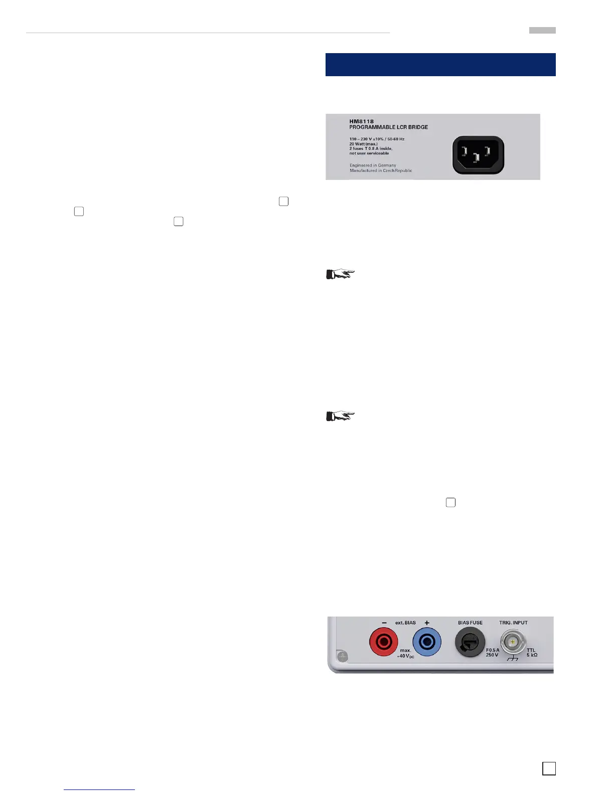
4.1 Connecting the instrument
Fig. 4.1: Power Input
Prior to connecting the instrument to the mains, check whether
the mains voltage conforms to the mains voltage range spe-
ciedon the rear panel.Thisinstrumenthasa wide-range
power supply and hence requires no manual setting of the
mains voltage.
Warning!
This measuring instrument is solely destined for
use by qualied personnel well informed about
the dangers that go along with the measurement
of electrical parameters. For elementary safety
reasons this instrument must only be connected to
mains wall outlets with a safety ground connector.
The safety ground conductor must not be discon-
nected. It is important to always rst connect the
safety ground contact in the line cord with the
safety ground contact in the wall outlet before any
other connections to the instrument are made (I.e.
plug the line cord in rst of all).
As a general rule the instrument must always be
turned on and be ready to operate rst before a
measuring signal is applied. If a functional problem
of the instrument becomes obvious, no further
measurements should be entertained; the measu-
ring signals should be removed and the instrument
turned off.
The fuse holder of the BIAS FUSE
45
, i.e. the external BIAS input,
is accessible on the rear panel. Prior to exchanging a fuse the
instrument must be disconnected from the mains. Then the
fuse holder may be removed with a suitable screw driver, using
the slot provided. Afterwards the fuse can be removed from the
holder and exchanged. The holder is spring-loaded and has
to be pushed in and turned. It is prohibited to use „repaired“
fuses or to short-circuit the fuse. Any damages incurred by
such manipulations will void the warranty. The fuse may only
be exchanged by this type:
Fig. 4.2: Rear panel with fuse
Type of fuse:
Ceramicbody,lledwithreextinguishingmaterial
Size 6.3 x 32 mm; 400 V
AC
, C;, IEC 127, Bl. III; DIN 41 662
(alternatively DIN 41 571, p. 3), (F) 0,5 A
 Loading...


