Setting of instrument parameters
asthiseldisopen,theactualmeasuredvalueoftheDUT(=
Device Under Test) may be set as the reference by pressing
the
TRIG
button.
5.1.15 Constant voltage CST V:
At this point the constant voltage (AC) may be turned on/off.
Insomecasesatestmayrequiretheuseofaspecicmea-
surement voltage due to the source impedance which is not
available together with the normal source impedance of the
respective range . In order to achieve this, a constant voltage
(CST V) may be switched in with the menu function SETUP.
For all measurements with BIAS voltage or current
the constant voltage (CST V) must be turned on!
The menu function SETUP is selected by pressing the SELECT
button
3
. Use the arrow buttons
8
Änderungen vorbehalten
Bezeichnung der Bedienelemente
2 Bezeichnung der Bedienelemente
Gerätevorderseite
1
POWER (Taste)
Netzschalter; Netzanschluss auf der Geräterückseite
2
GATE (LED)
Die GATE-LED leuchtet während der gesamten Dauer einer
Messung. Dies entspricht der gewählten Torzeit und einer
Synchronisierungszeit.
3
REMOTE (LED und Taste)
Die REMOTE–LED leuchtet, sobald das Gerät über die Schnitt-
stelle angesprochen wird. Um zur manuellen Betriebsart
zurückzukehren, ist die REMOTE-Taste zu drücken.
4
Display (LCD-Anzeige)
Anzeige des Messergebnisses und verschiedener Zusatzin-
formationen
5
ESC (Taste)
Escape-Taste in der Menüsteuerung
6
ENTER (Taste)
Enter-Taste in der Menüsteuerung
7
SELECT (Taste)
Menüaufruf bzw. Auswahl eines Menüpunkts
8
(Tasten)
Pfeiltasten zur Menüsteuerung und Parametereinstellung
9
Drehgeber
Drehknopf zur Parametereinstellung
10
GATE TIME (Taste)
Einstellung der GATE-Zeit
11
LEVEL B (Taste)
Einstellung des Triggerlevels von Kanal B
12
LEVEL A (Taste)
Einstellung des Triggerlevels von Kanal A
13
16
1 : 10 (Taste)
Eingangssignalabschwächer, Gesamtabschwächung 100-fach
14
DC (Taste)
Wahl der Kopplungsart des entsprechenden Kanals:
Taste DC leuchtet = DC-Kopplung
Taste DC aus = AC-Kopplung
15
Slope (Taste)
DurchDrückendieserTastewirddieTriggerankegewählt.
Leuchtet die Taste, wird auf die negative Flanke getriggert. Ist
die Taste unbeleuchtet, erfolgt die Triggerung auf die positive
Flanke.
17
50 Ω (Taste)
Zuschalteneines50Ω-WiderstandszumEingangzurAnpas-
sungbei50Ω-Systemen
18
LP 50 kHz (Taste)
TiefpasslterzurVermeidungunerwünschterHF-Triggerung
bei niederfrequenten Signalen
19
23
TRIG (LEDs) Triggerindikatoren
20
22
INPUT A, INPUT B (BNC–Buchsen)
Messsignaleingänge DC-200 MHz
21
AUTO TRIG (Taste)
Aktivierung des Auto-Triggers. Die Taste AUTO TRIG leuchtet,
wenn die automatische Triggerung aktiv ist.
24
INPUT C (SMA-Buchse)
Messsignaleingang 100 MHz – 3 GHz
25
RESET · V
Taste mit Doppelfunktion:
1. Durch Drücken dieser Taste wird die laufende Messung
unterbrochen, die Anzeige gelöscht und die Messung neu
gestartet.
2. Bei Einstellung des Triggerlevels mit den Zifferntasten
wird
der eingegebene Wert mit der Einheit Volt (V) übernommen.
26
TRIG · GHz/s (Taste)
Taste mit Doppelfunktion:
1. Auslösen einer Messung im ARMED-Betrieb.
2. Bei Einstellung der Gatetime mit den Zifferntasten wird der
eingegebene Wert mit der Einheit Sekunde (s) übernommen.
27
HOLD · mV (Taste)
Taste mit Doppelfunktion:
1. Durch Drücken dieser Taste wird der zuletzt im Display
angezeigte Messwert eingefroren.
1 2 3 4 5 6 7 8 9
10 11 12
13
14 15
16
17 18
1920212223242526272829303132
7
and the knob
6
to set the parameter CST V to ON. This will set the source
impedanceto25Ω.Forallcomponentswithimpedances>25Ω
the voltage will remain nearly constant. In order to prevent
overloading the bridge the selected range may automatically
change, depending on the impedance of the component. Ope-
rating in constant voltage mode decreases the accuracy by 2.
The following table lists the impedance ranges for constant
voltage operation (CST V ON):
Measurement Source Impedance of the
range Impedance component
1 25Ω 10.0µΩ — 3.0Ω
2 25Ω
3.0Ω —100.0Ω
3 25Ω
100.0Ω — 1.6kΩ
4 25Ω
1.6kΩ— 25.0kΩ
5 25Ω
25.0kΩ — 2.0MΩ
6 25Ω
2.0MΩ —100,0MΩ
The following table lists the impedance ranges when the constant
voltage mode is switched off (CST V OFF):
Measurement Impedance of the
range component
1 to 2 Z > 3.33Ω
2 to 3 Z >400.00Ω
3 to 4 Z > 6,67kΩ
4 to 5 Z >100.00kΩ
5 to 6 Z > 2.22MΩ
2 to 1 Z < 2.7Ω
3 to 2 Z <324.0Ω
4 to 3 Z < 5.4kΩ
5 to 4 Z < 81.0kΩ
6 to 5 Z < 1,8MΩ
There may be conditions which cause an OVERRANGE display.
This may happen if both constant voltage and manual operation
is selected. In order to sidestep this problem choose manually
a higher range or switch to automatic mode (AUTO).
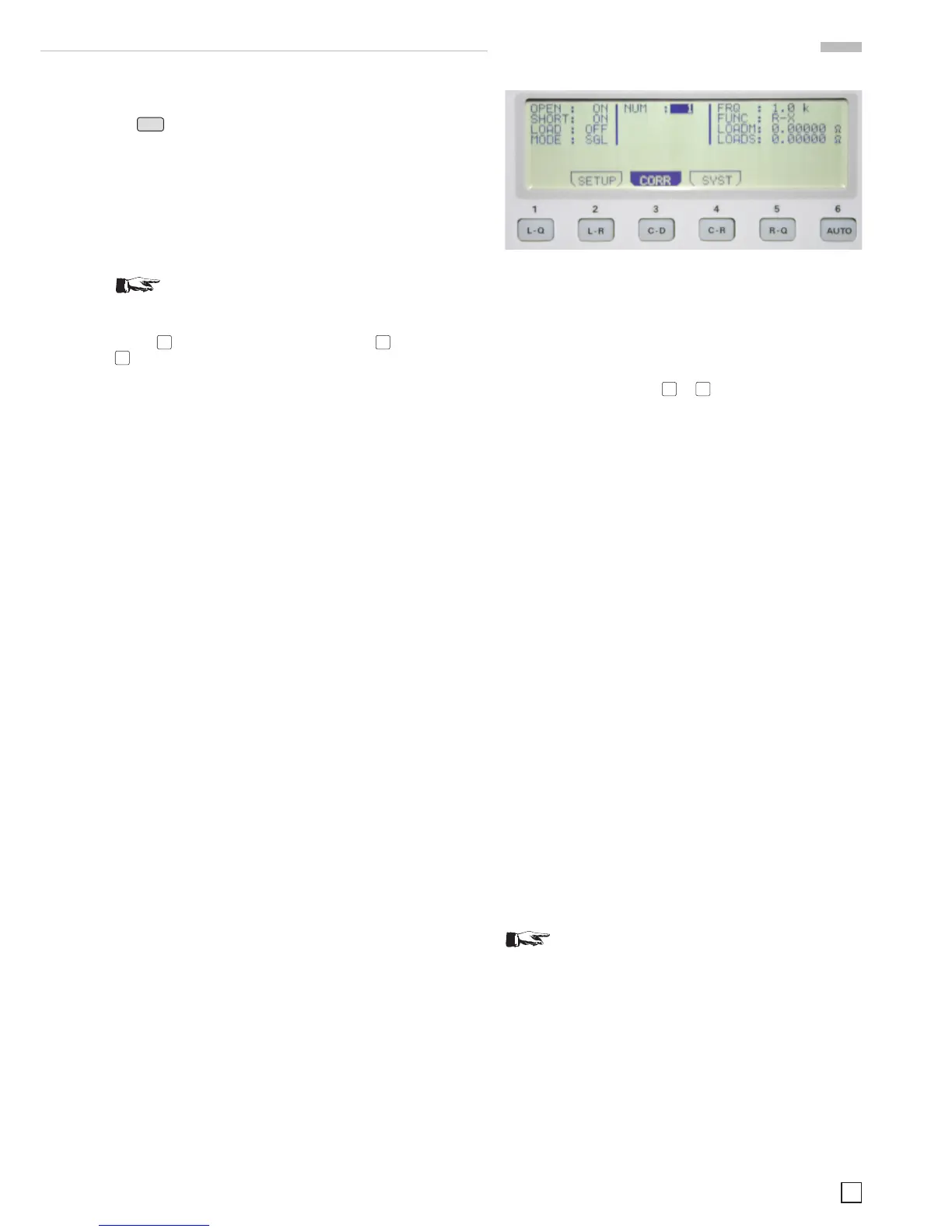
5.2 Menu function CORR
The submenu of CORR allows the selection of:
5.2.1 Calibration OPEN:
At this point the open circuit calibration can be turned on/off (pro-
cedure description at chapter 6.1).
5.2.2 Calibration SHORT:
At this point the calibration with shorted terminals can be turned
on/off (procedure description at chapter 6.2).
5.2.3 Calibration LOAD:
At this point the calibration with a known load impedance can
be turned on/off. For any measurements with load impedance
calibration the desired function must be selected manually
by pressing of the buttons
28
...
39
(procedure description at
chap. 6.3).
5.2.4 NUM:
Here, one of 6 available LOAD impedances 0 to 5 can be selected.
5.2.5 Frequency FRQ:
The measuring frequency of the load impedance (LOAD) may
be selected from 20 Hz to 200 kHz.
5.2.6 Function FUNC:
At this point the reference values for the load impedances
LOADM and LOADS can be selected. The following functions
are available:
Ls-Q, Lp-Q, Ls-Rs,
Lp-Rp, Cs-D, Cp-D,
Cs-Rs, Cp-Rp, Rs-Q,
Rp-Q, Z-
Θ, Y-Θ,
R-X G-B
5.2.7 Reference value LOADM for the main
measurement value:
A measurement result may be stored in memory LOADM as
the reference value for the load impedance LOAD. The availa-
ble units are, depending on the parameter FUNC: H, mH, µH,
nH,F,mF,µF,nF,pF,Ω,mΩ
, kΩ,MΩ, or S, kS, mS, µS, nS, pS.
5.2.8 Reference value LOADS for the second
measurement value:
Here a measurement result may be stored in memory LOADS
as the reference for the load impedance LOAD. The available
unitsare,dependingonthefunctionFUNC:Ω,mΩ
, kΩ,MΩ, S,
kS, mS, µS, nS, pS or °.
Remark!
When using the calibration with a load, values must
be entered in both reference memories (e.g. if an
ohmic resistance is used for LOADM its value will
be stored in LOADM , and „0“ in LOADS.)
TheparametersLOADMandLOADScanbeused,ifitisdifcult
tocalibrateatestxtureorifitisconnectedvialongleads.In
such case it is not possible to realize a full open/short calibration
becausetheactualcircuitofthexturecannotbecompensated
by a simple equivalent circuit provided in the LCR bridge.
The bridge can hence remain in an uncalibrated state. By using
a known impedance at the measuring frequency the user can
compensate for the resulting measurement error.
Fig. 5.3: Display of the menu function CORR
 Loading...


