Mechanical installation
20 A0785-150 HBM: public T10FS
application. As an alternative, check thermal decoupling
by means of heat radiating elements such as multi‐disk
couplings.
5.2 Installation orientation
The measurement flange can be mounted in any
position. With clockwise torque, the output frequency is
10 kHz to 15 kHz. With HBM amplifiers or with the
“voltage output" option, a positive output signal (0 V ...
+10 V) is present.
In the case of the speed measuring system, an arrow is
attached to the head of the sensor to clearly define the
direction of rotation. If the measurement flange moves in
the direction of the arrow, connected HBM measuring
amplifiers deliver a positive output signal (0 V ... +10 V).
5.3 Installation options
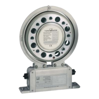
In principle, there are two possibilities for torque flange
mounting: with the antenna ring complete or dismantled.
We recommend mounting as described in Chapter 5.3.1.
If installation in accordance with Chapter 5.3.1 is not
possible (e.g. in the case of subsequent stator
replacement or mounting with a speed measuring
system), you will have to dismantle the antenna ring. It is
essential in this case to comply with the notes on
assembling the antenna segments (see “Mounting the
stator" and “Mounting the slotted disc").

 Loading...