Mechanical installation
T10FS A0785-150 HBM: public 35
5.8.1 Fixing the mounting elements
1. Place the rotor with the identification plate upward on
a flat base.
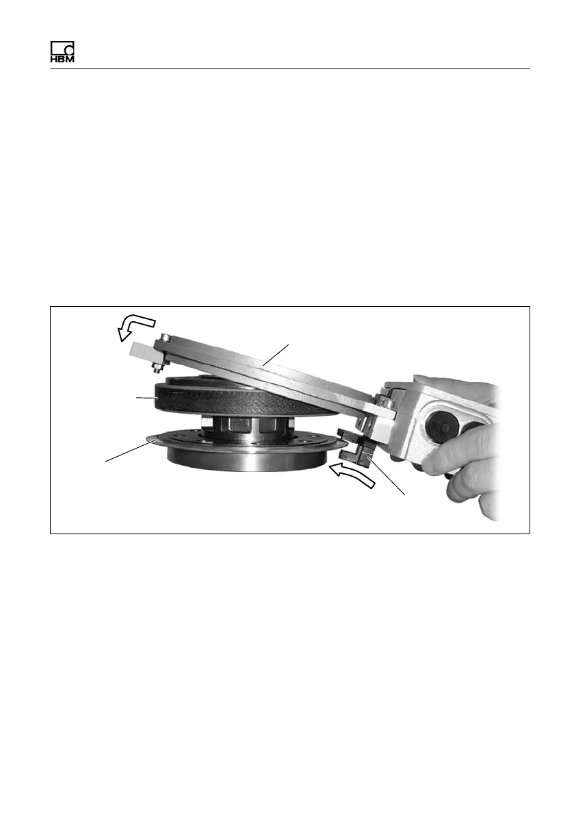
For the optical speed measuring system only:
Hold the stator at a slight slant and push it over the rotor
until the slotted disc is located in the optical sensor
(Step A, Fig. 5.9).
Tilt the stator over the rotor until the antenna ring
completely covers the transformer (Step B, Fig. 5.9).
B
A
Slotted disc
Sensor pickup
Transformer
Antenna ring
Fig. 5.9 Installing the mounting elements
2. Hold the stator centrally over the rotor and one after
the other, push the three mounting elements between
the transformer and the antenna ring. The mounting
elements should be evenly distributed around the
circumference (approx. every 120).
3. Screw the fastening screws of the mounting elements
into the tapped holes of the flange and gently tighten
them by hand.

 Loading...

