Settings
T10FS A0785-150 HBM: public 71
8.7 Form of speed output signal
In the factory setting, two 90 phase‐offset speed signals
(5 V symmetrical, complementary RS-422 signals) are
available at the speed output (connector 2). You can
double the pulse count set in each case by moving
switch S6 to the “On" position. Pin 3 then outputs the
direction of rotation as a static direction of rotation signal
(pin 3 = +5 V, pin 7 = 0 V compared to pin 8), if the shaft
turns in the direction of the arrow). At a speed of 0 min
-1
,
the direction of rotation signal has the last measured
value.
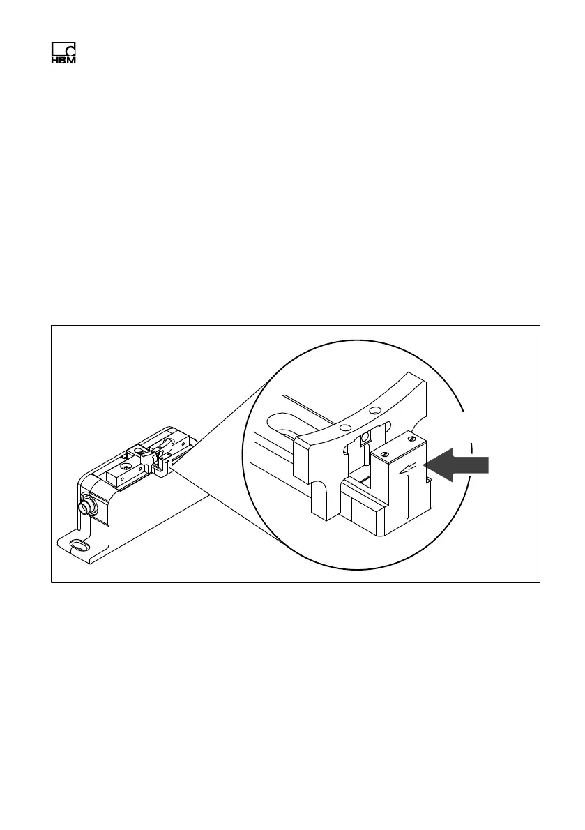
Direction of
rotation arrow
Fig. 8.11 Direction of rotation arrow on the head of the sensor
 Loading...


