Settings
64 A0785-150 HBM: public T10FS
8.5 Setting the pulse count
8.5.1 Magnetic speed measuring system
With the magnetic speed measuring system, a
magnetized rotor is sampled by means of an MR sensor
(magnetoresistive sensor). The sensor produces two
sinusoidal signals offset by 90, from which up to 10
evaluation points can be generated per pole (can be
adjusted with switches F1 ... F3). The output pulses can
again be divided by means of the subsequent electronic
system (switches S1 ... S4), thus making available a
greater selection of output pulse counts per revolution
(see Fig. 8.8).
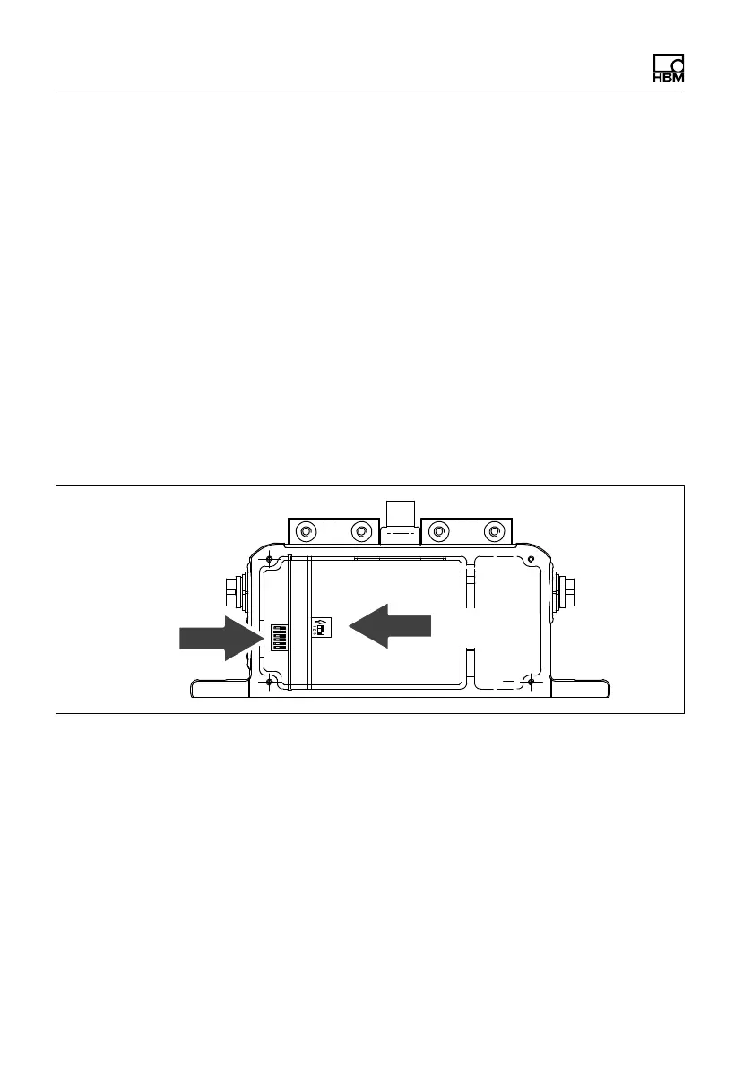
Switches
S1...S4
Switches
F1...F3
Fig. 8.7 Setting the pulse count; magnetic speed measuring
system

 Loading...

