Settings
T10FS A0785-150 HBM: public 73
8.9 Optical speed measuring system with
a reference pulse
In the case of the reference pulse option, a magnet is
integrated into the slotted disc of the speed measuring
system, that generates a pulse at each full revolution of
the rotor. The pulse can be picked up at connector 2
(see Page 52).
The reference pulse is synchronized with the speed
output signal (5 V
1
), 0°) and is output if the reference
marker is passed and a rising edge occurs during the
speed signal.
The pulse length corresponds to the length of a speed
increment, which depends on the chosen pulse count
and speed (for the calculation, see Page 64).
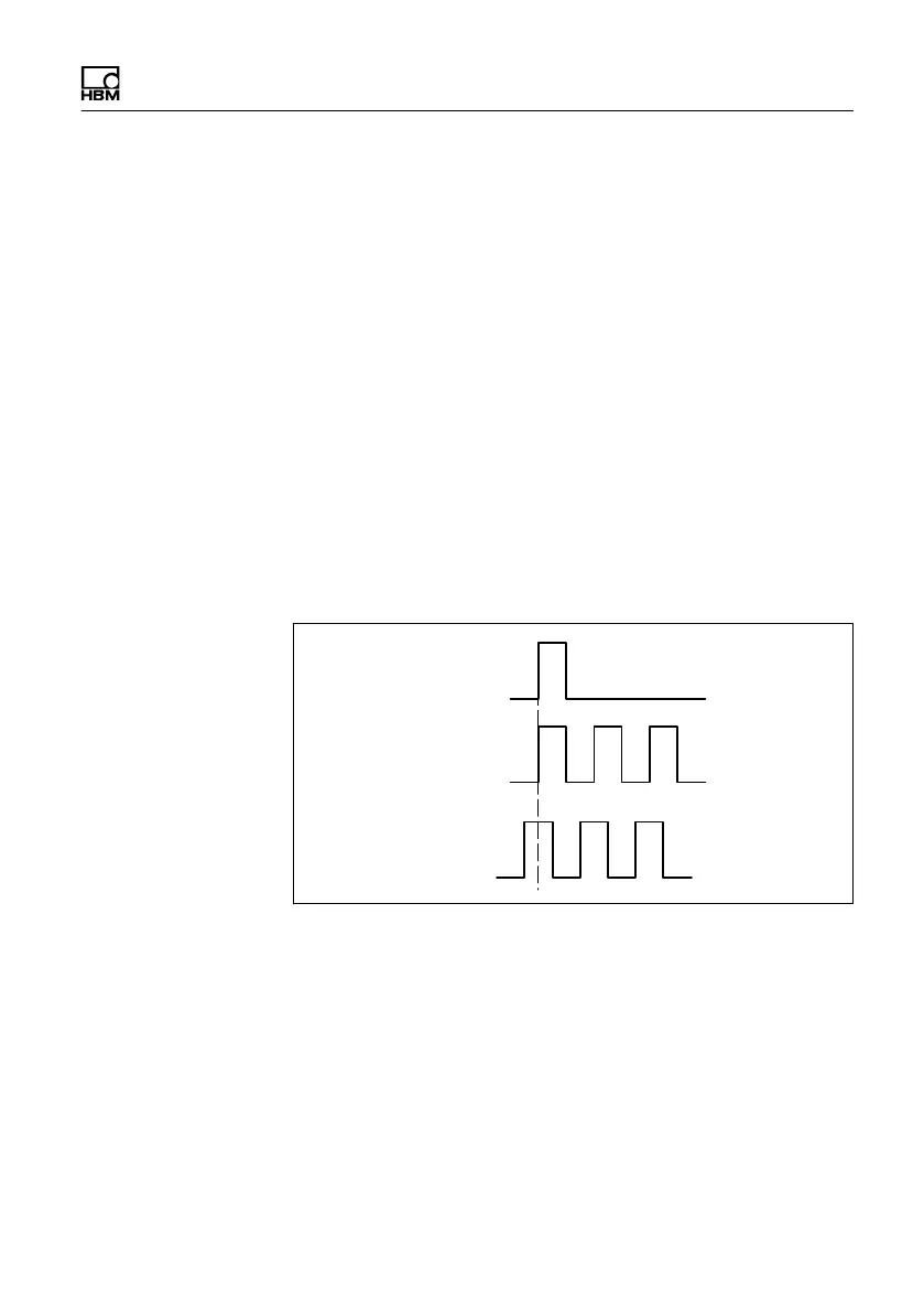
Reference pulse
Speed signal 0 °
Speed signal 90 °
5 V symmetrical
5 V symmetrical
5 V symmetrical
Fig. 8.14 Electrical condition of the reference pulse
When the speed measuring system and the reference
pulse are properly synchronized, LED L4 flashes
(minimum speed 2 min
-1
) and stays on permanently from
approx. 1000 min
-1
. If the LED is not on, please change
switch S8 (see Fig. 8.15).
1)
RS-422 complementary signals

 Loading...

