EasyManuals Logo

HBM T10FS User Manual

HBM T10FS
112 pages
To Next Page IconTo Next Page
To Previous Page IconTo Previous Page
Page #42 background imageLoading...
Page #42 background image
Mechanical installation
42 A0785-150 HBM: public T10FS
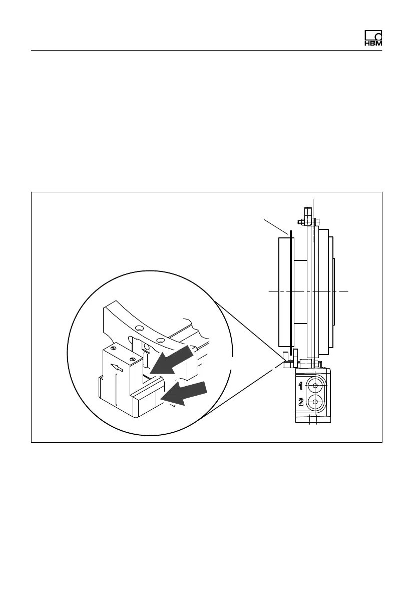
5.9.2 Optical speed measuring system
Axial alignment
There are markers in the optical sensor for axial
alignment (orientation lines). When installed, the slotted
disc should be exactly above these alignment lines.
Divergence of up to ±2 mm is permissible in measuring
mode (total of static and dynamic shift).
Slotted disc
Alignment lines
Fig. 5.14 Position of the slotted disc in the speed sensor

Table of Contents

Questions and Answers:

Question and Answer IconNeed help?

Do you have a question about the HBM T10FS and is the answer not in the manual?

HBM T10FS Specifications

General IconGeneral
BrandHBM
ModelT10FS
CategoryMeasuring Instruments
LanguageEnglish

Related product manuals