EasyManuals Logo

HBM T10FS User Manual

HBM T10FS
112 pages
To Next Page IconTo Next Page
To Previous Page IconTo Previous Page
Page #67 background imageLoading...
Page #67 background image
Settings
T10FS A0785-150 HBM: public 67
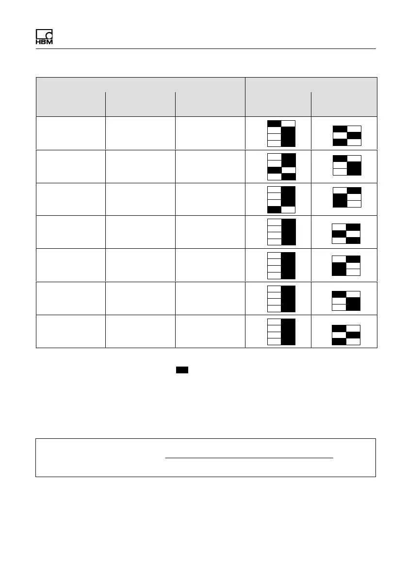
Switch positionOutput pulses/revolution
F1 ... F3S1 ... S42 kNVm ...
10 kNVm
500 NVm /
1 kNVm
100 NVm /
200 NVm
200 240 300
240 288 360
300 360 450
480 576 720
*)
600
1)
720
1)
900
960 1152 1440
1200 1440 1800
Fig. 8.8 Switch settings for pulse count/revolution
(
¢ switch lever)
1)
Factory setting
The output pulse count is calculated according to the
following formula:
outputpulsecount +
magneticpoles @ evaluationpointperpole
outputpulsedivision

Table of Contents

Questions and Answers:

Question and Answer IconNeed help?

Do you have a question about the HBM T10FS and is the answer not in the manual?

HBM T10FS Specifications

General IconGeneral
BrandHBM
ModelT10FS
CategoryMeasuring Instruments
LanguageEnglish

Related product manuals