10
9
8
7
6
5
4
3
2
1
Appendix
Reference
Guides
Alarms and
Emergencies
Patient
Management
Surgical
Implant and
Explant
Monitor
Peripherals
and
Accessories
HVAD
®
Pump Overview
Introduction
112 HVAD® Instructions for Use
6.3 HVAD
®
Pump Pre-Implant Test and Pump Assembly (continued)
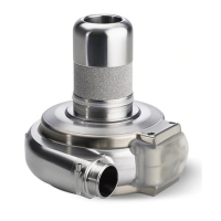
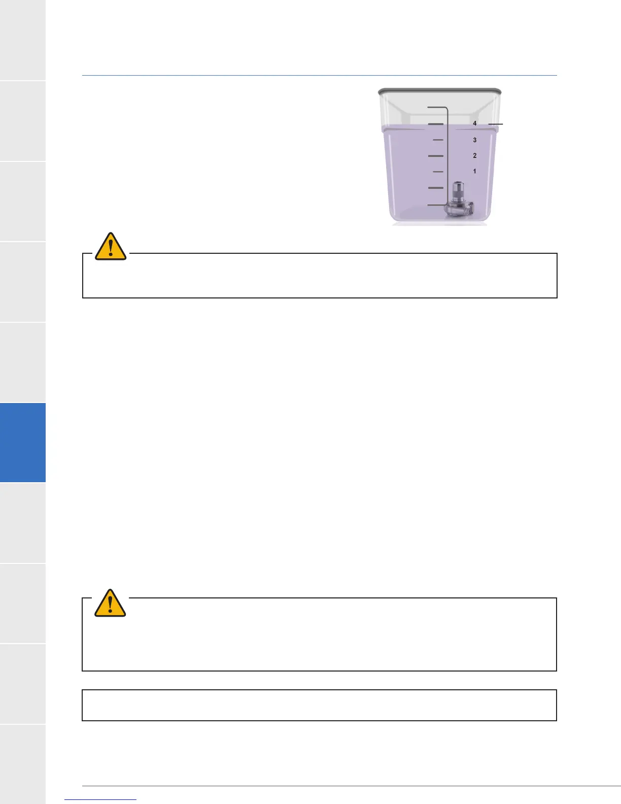
7.
solution to establish at least 4.0 inches (10.2 centimeters)
(Figure 100).
8. Attach the sterile driveline extension cable to the
HVAD
®
Pump and pass the distal portion of the cable
(labeled “Controller”) to the non-sterile assistant.
WARNING! ALWAYS check for an audible click when connecting the driveline to the controller or
driveline extension cable. Failure to ensure a secure connection may cause electrical fault.
9.
cable movement.
10. The non-sterile assistant should have the back-up controller and a charged battery ready
for use. Completely submerge the HVAD
®
Pump in the dextrose solution. Fill the pump with
dextrose and gently rotate it in the dextrose to allow any trapped air to escape.
11.
damage to the pump and [Low Flow] alarms.
12. When the HVAD
®
Pump is completely submerged in the sterile basin and is de-aired, point
to prevent dextrose from squirting out of the basin.
13. The non-sterile assistant should connect the driveline extension cable to the controller,
ensuring that there is an audible click when making the connection. Push the driveline
extension cable boot forward to cover the exposed metal driveline connector and the
mating connecting on the controller.
14. Connect the battery to the controller.
15. The pump will start at 1800 RPM.
WARNING!
®
HVAD
®
to implantation: The HVAD
®
®
Pump Pre Implant Test, a low priority alarm will sound since one of the controller
power ports is empty.
Figure 100: Submerged pump
4.0 in (10.2 cm)
drawn to scale.