10
9
8
7
6
5
4
3
2
1
Appendix
Reference
Guides
Alarms and
Emergencies
Patient
Management
Surgical
Implant and
Explant
Monitor
Peripherals
and
Accessories
HVAD
®
Pump Overview
Introduction
118 HVAD® Instructions for Use
6.4 Surgical Implant Procedure (continued)
Outow Graft Anastomosis
1.
without kinking or overstretching.
2.
graft will be placed.
3.
polypropylene (or similar material) sutures.
4. Remove the partial occlusion clamp from the aorta and ensure an intact anastomosis
without bleeding, while keeping the HVAD
®
WARNING!
WARNING!
™
grafts in saline for longer than 5 minutes. Longer periods
of soaking in saline may disrupt the gel matrix, resulting in bleeding.
CAUTION: ALWAYS use round body taper point needles when implanting Gelweave
™
prostheses to
thrombus formation.
Driveline Placement
Select the location where the driveline will exit the skin.
Consider the position of major organs and structures
when determining the path of the tunneler. Massage
antibiotic solution into the external surface of the
driveline’s woven polyester velour.
The tunneler (Figure 109) is designed so that the handle
can be attached and detached. To attach the handle
to the tunneling rod, depress the locking pin, insert the
tunneling rod into the handle until it bottoms out, release
the locking pin and rotate the handle until the locking pin
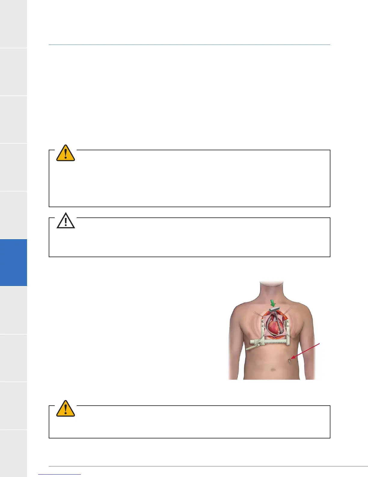
pops out. Using the tunneler, tunnel the driveline lead to
the point of exit. Adjust distance of exit site from costal
the costal margin.
WARNING! ALWAYS position the driveline exit site so that the tunneler does not contact any vital organs
or structures.
Figure 109: Tunneler
Exit site