10
9
8
7
6
5
4
3
2
1
Appendix
Reference
Guides
Alarms and
Emergencies
Patient
Management
Surgical
Implant and
Explant
Monitor
Peripherals
and
Accessories
HVAD
®
Pump Overview
Introduction
90 HVAD® Instructions for Use
5.3 System Screens (continued)
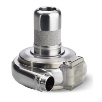
Speed/Control Tab (continued)
®
Pump button is
colored and labeled according to the running state of the HVAD
®
Pump:
®
Pump is pumping; the button is RED and labeled STOP.
To stop VAD, press STOP.
®
To start VAD, press START (Figure 69).
Figure 69: System Screen – VAD Start
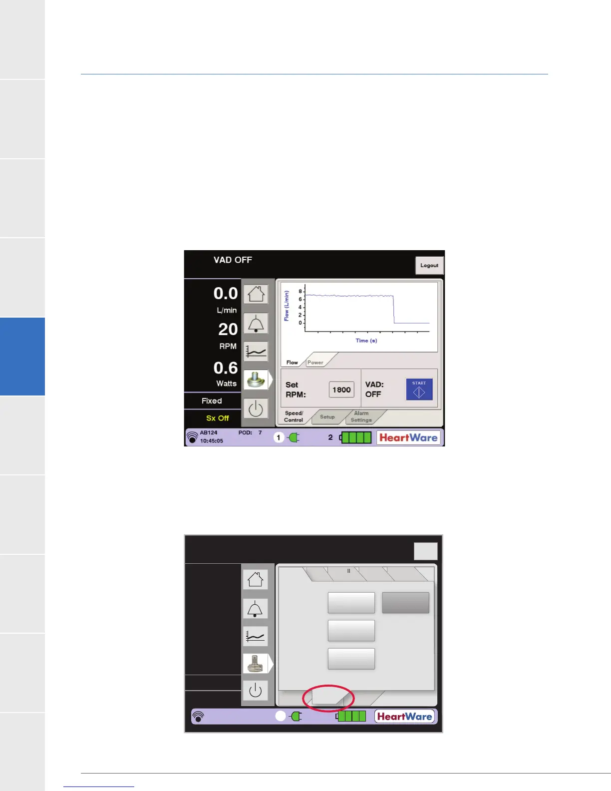
Setup Tab
When the Setup tab is pressed, four additional tabs are displayed and include: Patient, VAD,
Controller and Monitor (Figure 70). The function of each is described below.
Figure 70: Setup Tab
Flow (L/min)
Time (s)
Logout
8
6
4
2
0
Speed/
Control
Alarm
Settings
Controller
SW
Monitor
Controller
VAD
Spee
/
n
r
l
rm
Settin
s
n
r
e
W
M
n
r
n
r
e
VA
Patient
Setup
Patient ID:
Hematocrit
Implant
Date:
AB124 Log Files
05/13/11
30%
2
3.6
2500
3.0
L/min
RPM
Watts
Fixed
Sx Off
AB124
POD: 6
14:13:19
1