User Manual of PanoVu Series Network Camera
Appendix 9 Alarm In/Out Connections
Note:
This section is only for the cameras with alarm in/out functions.
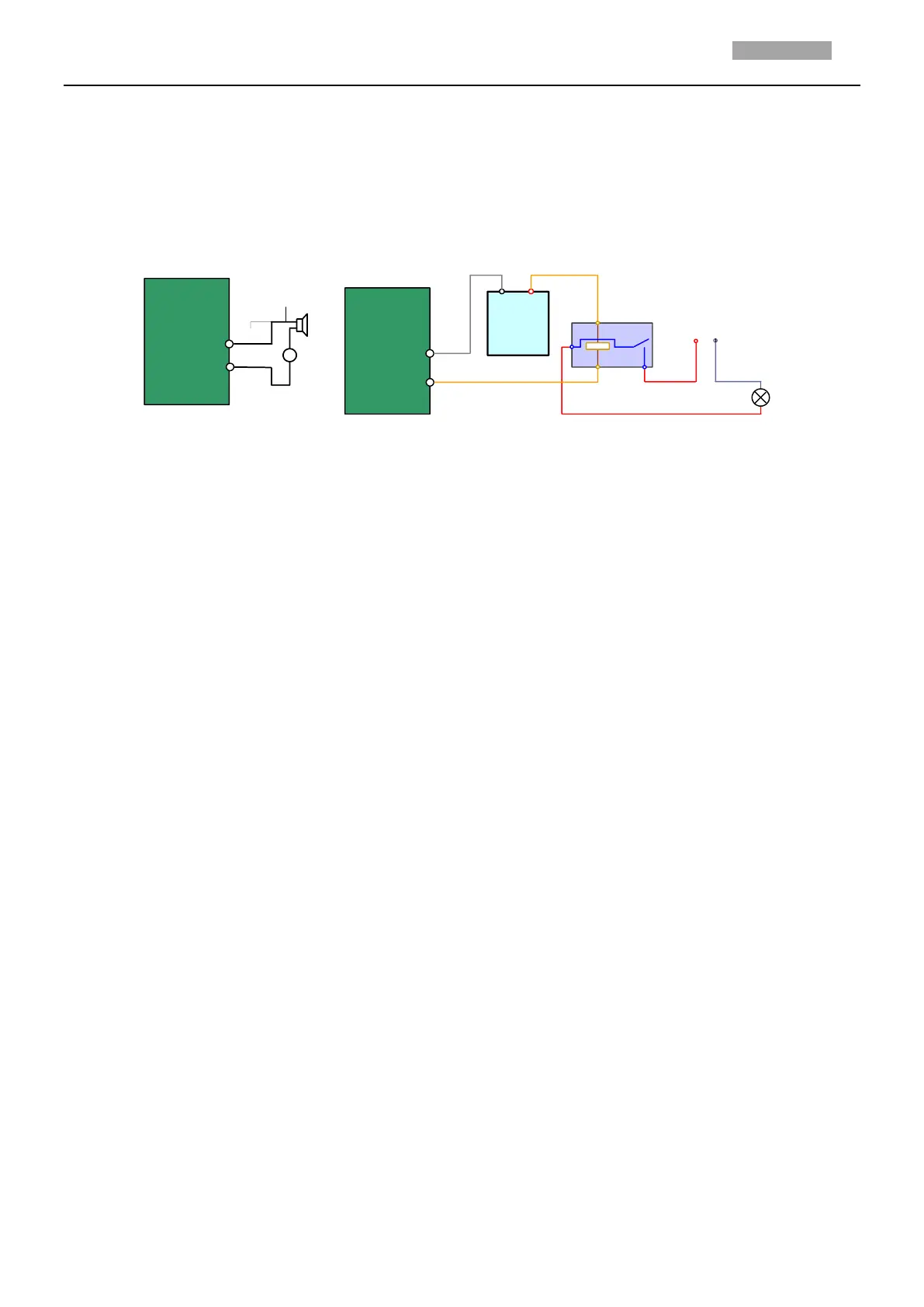
The camera can be connected with alarm inputs (0~5VDC) and alarm outputs. Refer to the following
diagrams for alarm output:
JQC-
3FG
Relay
30VDC
GND OUT
L N
~220V AC
Relay Output
Dome
(10 A 250VAC)
Diagram (left)
Diagram(right)
1A
OUT(n)
OUT(n)
+
-
DC
DC Load
Relay Output
Dome
OUT(n)
OUT(n)
Figure A.9.1 Alarm Out Connections
The alarm provides the relay output (no voltage), and the external power supply is required when it
connects to the alarm device.
For DC power supply (left diagram), the input voltage must be no more than 30VDC, 1A.
For AC power supply, the external relay must be used (right diagram) to prevent damages to the
camera and avoid risk of electric shock.
 Loading...