43
Measuring Insulation Resistance
IMPORTANT
• Insulation resistance is unstable. The indication may not stabilize depending on
the object under measurement.
• Depending on the charging current owing to the capacitance component of the
object under measurement and the associated absorption current, a value smaller
than the actual resistance value may be displayed after measurement starts. The
display value may then gradually increase and approach the actual resistance value.
• During measurement, if the resistance of the object under measurement suddenly
drops or if the test lead tips are short-circuited, the instrument stops voltage
generation as a safety measure. (This applies to a test voltage of 1100 V or more.)
See “Breakdown function” (p. 109).
• If the rotary switch is turned o during measurement, automatic discharge is
performed before power is turned o.
• If the battery runs low during measurement, the instrument automatically stops
measurement. After automatic discharge is performed, the display changes as
follows and the power is turned o.
[Lo bAtt] → [P.oFF]
• When measuring a capacitive load, the current may ow in reverse if the voltage
charged in the object under measurement is larger than the set output voltage
and for other reasons such as output voltage uctuations. If the measured
current value is negative, the current indication blinks.
• Turn the rotary switch to OFF after use.
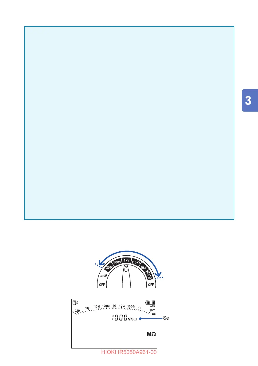
1
Turn the rotary switch to one of the selections between test voltage 250 V
and
2505k
▲
▼
V
.
You can also press the and keys to set the desired test voltage.
Set voltage
TIMER
PI DAR SV
Ramp
DD