44
Measuring Insulation Resistance
2
Connect the test leads to the instrument. (p. 35)
3
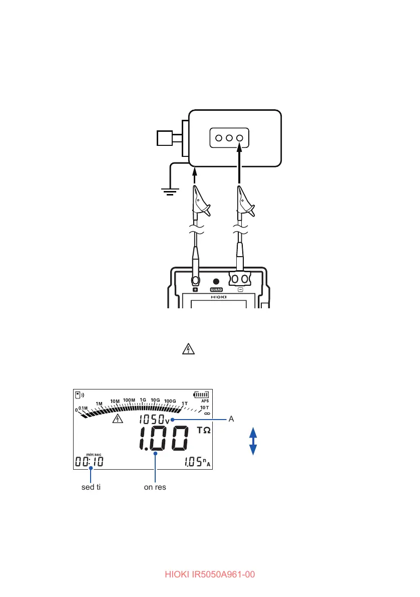
Connect the test leads to the object under measurement.
Clip the alligator clip at the end of each test lead to the object under
measurement.
Example of the object to be
measured: Motor
Test lead (Red)
Attach to a metal
chassis or a
ground terminal.
Test lead (Black)
Attach to a metal
part of the power
supply terminal.
4
Hold down the MEASURE key for more than one second to start
measurement.
Voltage is generated, and the mark and MEASURE key start blinking.
The display changes from the set voltage to the actual output voltage. A voltage
approximately 5% higher than the set level is output.
Actual output voltage
Insulation resistanceElapsed time
Set voltage
Press the ▲ key to
display the set voltage
for two seconds.
PI DD
•
During measurement, if the output voltage is lower than the set voltage, the
voltage indication blinks.
• During measurement, if the measured current is negative, the current indication
blinks.