56
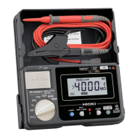
PV Insulation Resistance Measurement Function (IR5051 Only)
Measurement
1
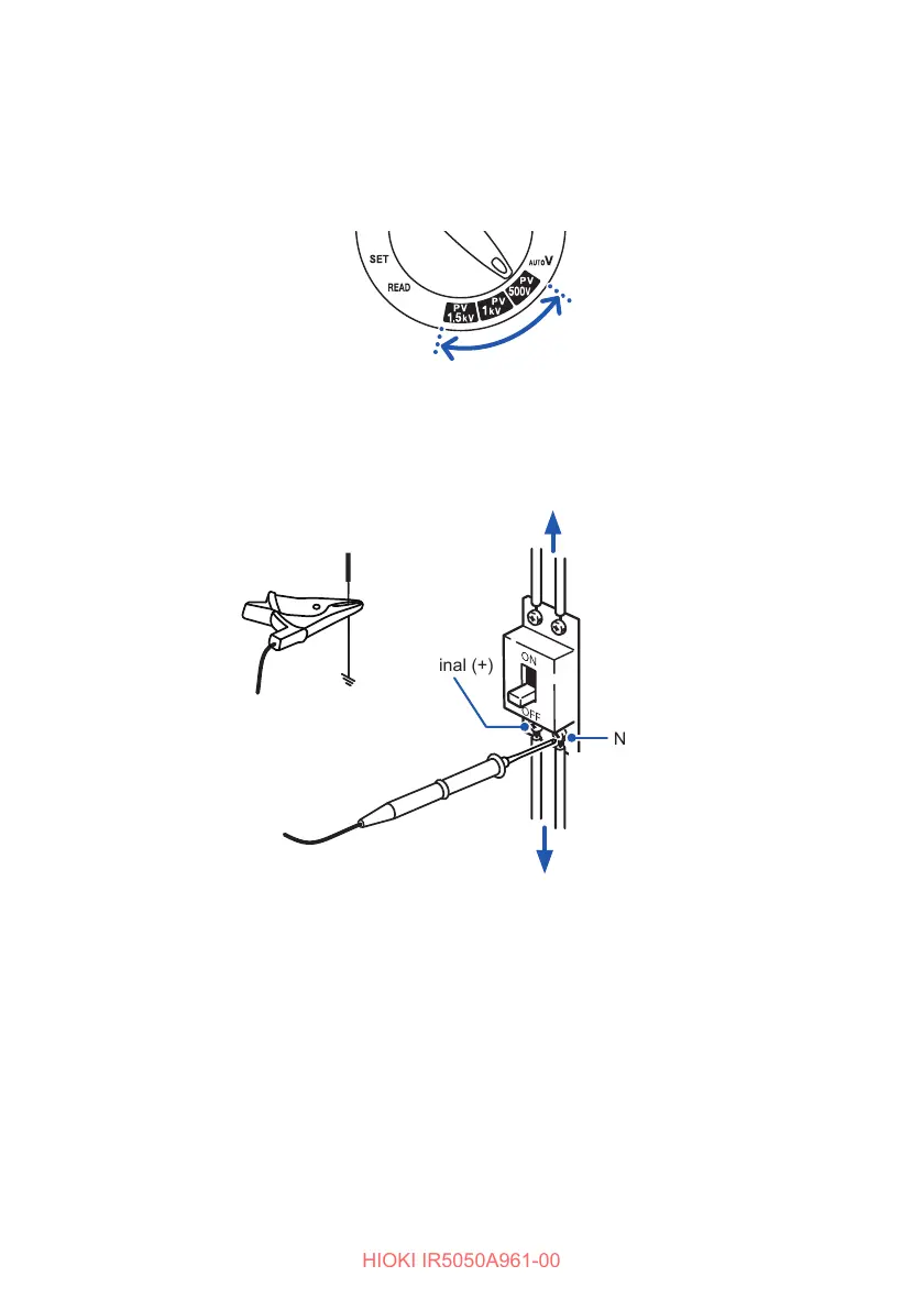
Turn the rotary switch to test voltage PV500V, PV1kV, or PV1.5kV.
You can also press the and keys to set the desired test voltage.
2
Connect the test leads to the instrument. (p. 35)
3
Connect the black test lead to the ground terminal.
4
Connect the red test lead to the N terminal on the PV string side.
P terminal (+)
4
Ground terminal
(Black)
(Red)
3
Disconnector
String
Power conditioner, main switch
N terminal (−)
There is a risk of insulation deterioration when voltage is generated between the
N terminal and ground. When there is voltage in the object under measurement,
the backlight blinks in red by the voltage detection function.