Installation BRS20/30/40/50
Release
02
11/2018
41
Figure 9: Mounting on the DIN rail
Proceed as follows:
Slide the upper snap-in guide of the device into the DIN rail.
Push the device downwards and onto the DIN rail.
Snap-in the device.
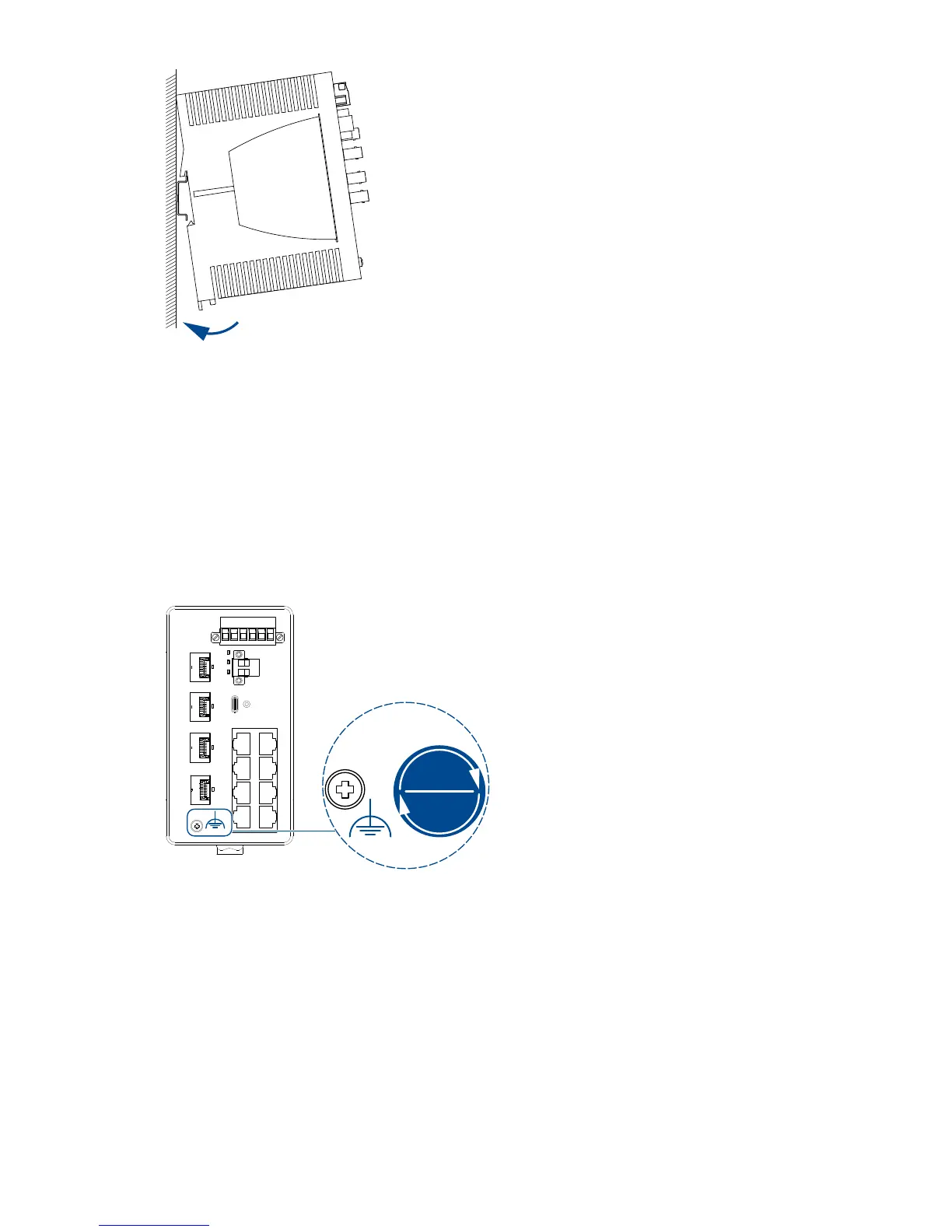
2.2.2 Grounding the device
Figure 10: Position of the ground connection on the device; tightening torque.
The device variants featuring supply voltage with characteristic value T
and F have a connection for functional grounding.
The housing is grounded via the separate ground screw on the bottom left of
the front side of the device.
Proceed as follows:
Ground the device via the ground screw.

 Loading...