3-12
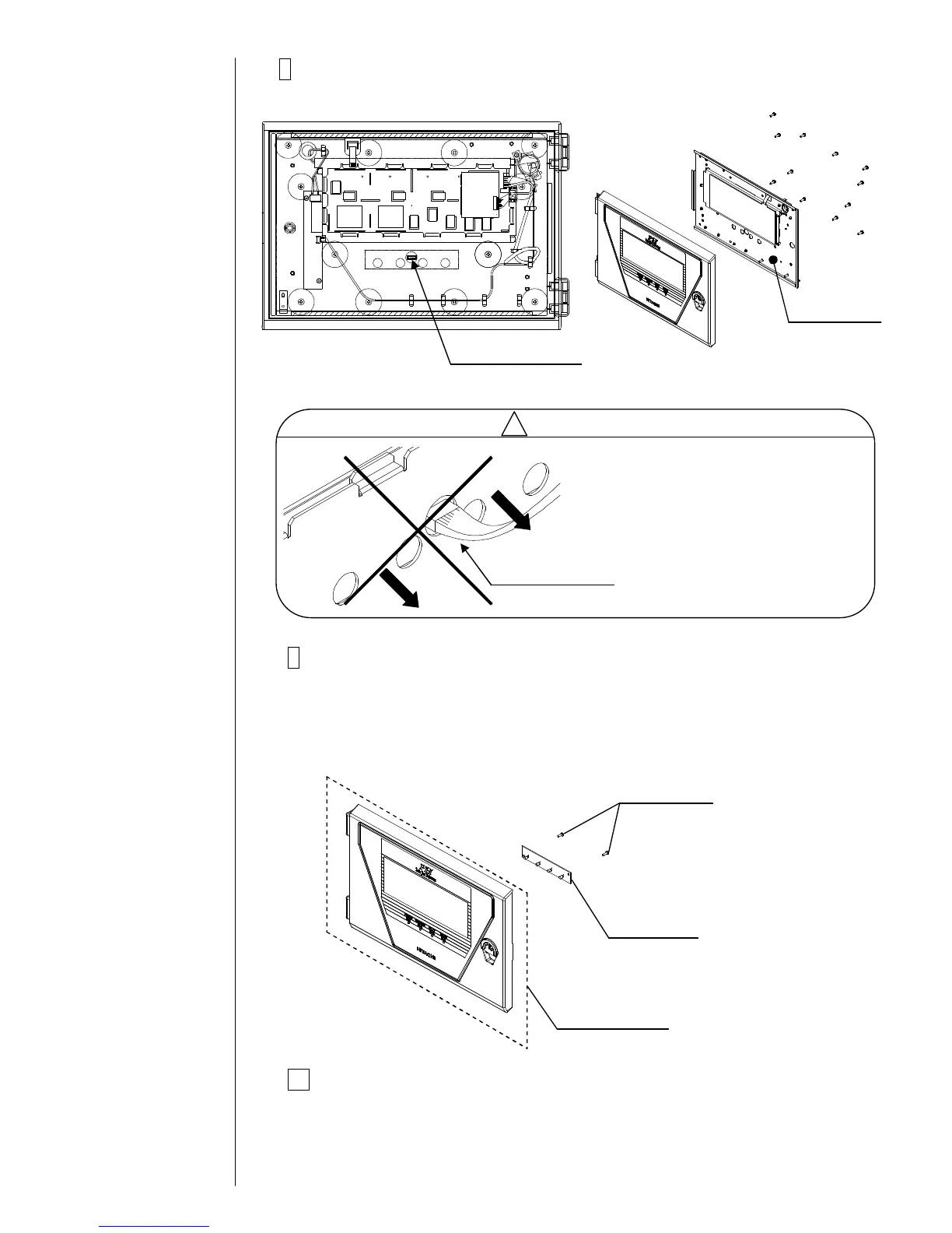
8Remove the fixing screws (12 pieces) of the LCD base and
remove the LCD base.
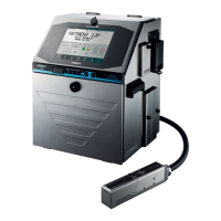
9Remove the fixing screws (2 pieces) of EZJ97 board.
Remove the front panel assembly and install a new front panel assembly
by performing opposite procedure.
[Note] When installing a new front panel assembly, note that the dusts
doesn't enter between the front panel and the touch panel.
10Return the unit to its original state by performing the procedure
in reverse order.
[Note] Insert the connectors to right places.
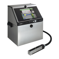
Before removing the LCD base,
confirm to remove the connector
for EZJ97 board.
When the LCD base is removed
with the connector connected, the
harness might be damaged.