1-32 ● Connection of signals
(b) When a dedicated power supply is used
If the print target detector current consumption is more than 80 mA, furnish a
dedicated power supply. In this instance, make wiring connections and perform
setup as indicated below.
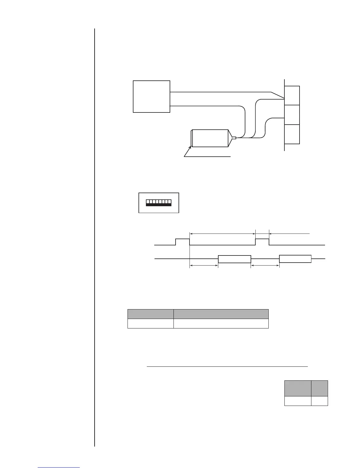
(i) Print target detector wiring method
DC12VDedicated
power supply
TB1
Print target detector
GND
+12V
GND
(ii) Setup procedure
Turn OFF switch SW2-5 on the EZJ95 board (terminal).
(Switch 2 is inside the cover. Do not operate it unless you have finished the ser-
vice education.)
* The minimum value for the time of preparing for printing varies with the print
dot matrix, calendar setup, and count setup. Approximate time values are
indicated in the table below.
Print target
detection signal
Printing operation
*Time of preparing
for printing
ON
Printing
*Time of preparing
for printing
(Printing interval)
OFF
3 ms minimum
(Print start delay
adjustment = 0)
ON
OFF
(Switch is black.)
+12V
(c) Relationship between print target detection signal and printing operation
3 ms minimum
Printing
Nozzle size Approximate Time
65µm 10 ms
The required time is precisely calculated using the following formula. It varies with
the pre-selected vertical dot count, character width, and ink drop use percentage.
Time required for preparing for printing = (One-scan time x (N+1)) + K (ms)
One-scan time=
(vertical dot count + character width) x ink drop use percentage
excitation frequency (kHz)
(ms)
N: (Integer that satisfies the equation one-scan time x N) >= a
K: 3 (ms)
Excitation frequency : 68.9 (In the case of 65 μm nozzle, JP-K67)
Nozzle
size
a
65µm 7
1
2
3
+12V
Signal
GND
12345678