●Connection of signals 1-33
In the case of following speed, the number of encoder pulses indicated below is
astandard minimum value of a printing space.
Minimum time of 1 pulse=
(vertical dot count + character width) x ink drop use percentage
excitation frequency (kHz)
(ms)
Necessary number of
encoder pulses
K+a
Minimum time of 1 pulse
x Pulse rate division factor (pulse)
=
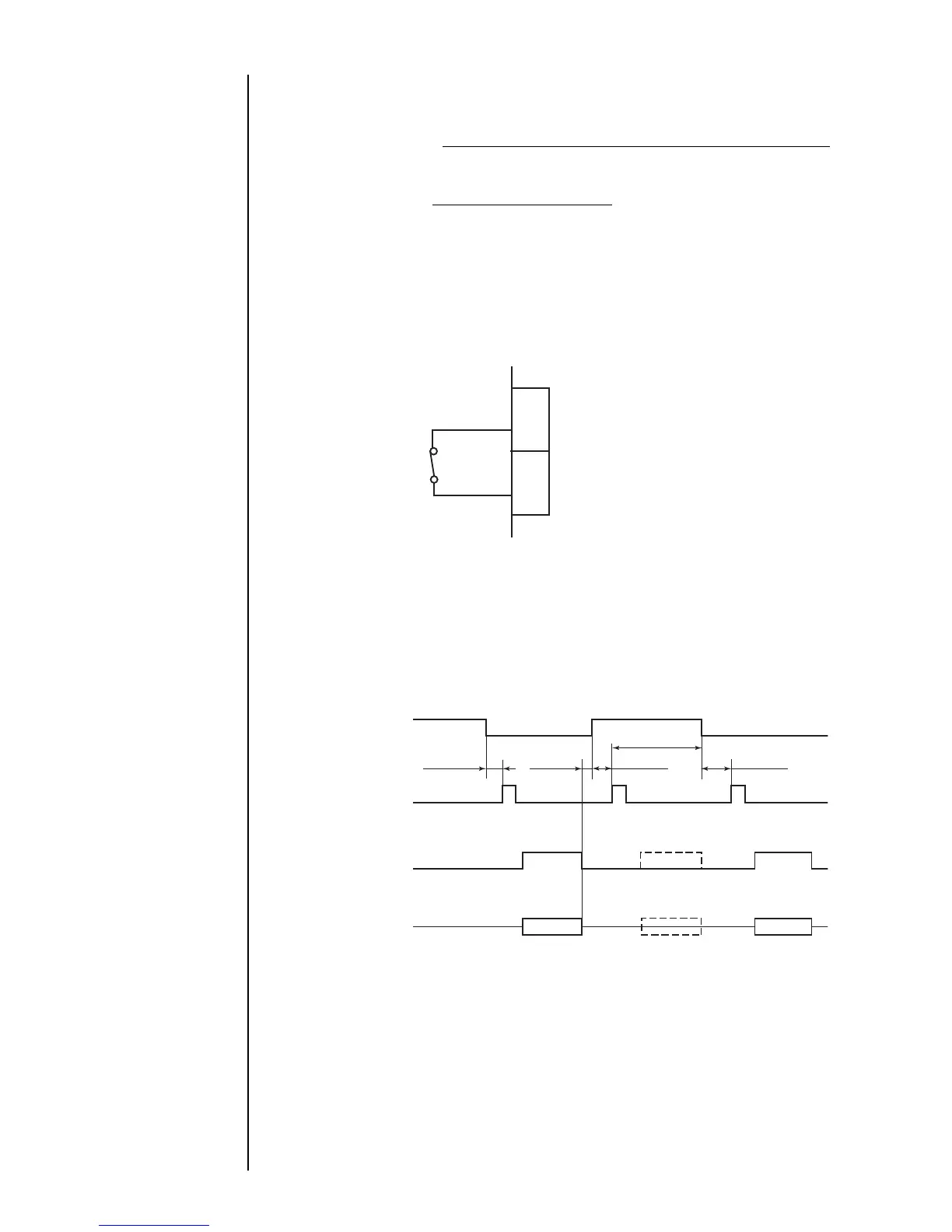
1.5.3-5 Printing stop signal
The following describes the wiring of the signal that is entered from the outside to
inhibit printing. (Note that the ready output signal remains unchanged even if this sig-
nal is entered from the outside.).
(No-voltage contact)
A current of about
12 mA flows.
TB1
4
5
Input specifications
●A no-voltage contact must be used for input.
●In the case of noncontact, the following
requirements must be met.
Withstanding voltage : 12 VDC or more
Maximum drive current: 12 mA or more
Residual voltage
: 2 V or less
Leak current : 0.1 mA or less
Drive method : Open collector
When the input is ON - While the IJ printer is in the ready state, it does not make prints
even if the print target detector turns ON. However, if any
printing operation is being performed, it does not come to a
halt.
When the input is OFF - While the IJ printer is in the ready state, it starts making prints
upon print target detector ON.
Print stop signal
Print start signal
Print stop signal
Printing-inprogress
signal
Printing operation
ON
OFF
OFF
OFF
ON
ON
50 ms or more
0 ms or
more
20 ms or more
50 ms or more
50 ms or more
Printing
[No Printing]
Printing
● The signal level is Low in the ON state or High in the OFF state.
● The tracking function cannot be used.
In the tracking mode, the printing stop time cannot be generated by the print stop
signal.
● In the continuous print mode, the operation is performed in accordance with the print
start signal that is generated inside the IJ printer.
Signal
GND