●Connection of signals 1-35
(d) Setup for dedicated power supply use
In the same manner as in cases where no dedicated power supply is used, refer to step
(b)-(i) above and specify whether or not to enable the product speed matching feature.
See the table below and set switch SW2 on the EZJ95 board (I/O board) in accordance
with the supply voltage (12 VDC or24 VDC). In this instance, the same setup applies
to the totem pole output and open collector output.
(Switch 2 is inside the cover. Do not operate it unless you have finished the service
education.)
(iii) From the print specifications screen, set the character width as shown in the
following table (the setting varies with the ink drop use percentage).
Ink drop use percentage setting Character width setting
1/1 002
1/2 001
1/3 to 1/16 000
NOTE: For the 40μm nozzle version, an ink drop use percentage of 1/1 cannot set.
(See Section 3.4 Setting Character Height and Character Orientation.)
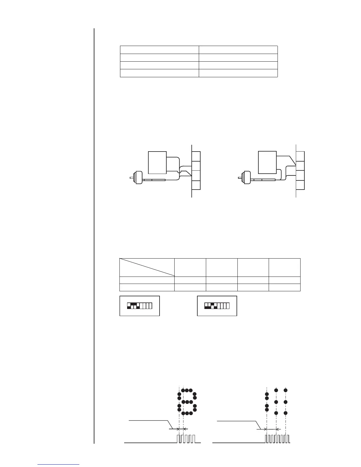
(c) Wiring for dedicated power supply use
If the rotary encoder current consumption exceeds 80 mA or a 24 VDC type rotary
encoder is used, furnish a dedicated power supply and make wiring connections as
indicated below.
For totem pole output
DC dedicated power supply
Rotary encoder
+V
GND
+V
GND
Signal
TB1
For open collector output
DC dedicated power supply
+V
GND
+V
Rotary encoder
TB1
1234
DC12V OFF ON ON OFF
DC24V OFF OFF ON OFF
SW2
Supply voltage
(e) Setting the rotary encoder pulse count and pulse rate division factor
When the rotary encoder is used, prints are made by conducting one scan after another
in accordance with the speed synchronization signal from the rotary encoder and the
pulse rate division factor (see the figure below).
To assure fixed character width, it is necessary to install the rotary encoder in such a
manner that the speed synchronization signal varies in proportion to the print target
transport speed.
<Printed character>
Horizontal direction
dot pitch (scan)
Speed synchronization
signal
When pulse rate division factor is 1/1
<Printed character>
Horizontal direction
dot pitch (scan)
Speed synchronization
signal
When pulse rate division factor is 1/3
6
7
8
9
+12V
Signal
GND
Signal
6
7
8
9
+12V
Signal
GND
ON
OFF
DC12V
ON
OFF
DC24V
(Switch is black.)
12345678 123456 78