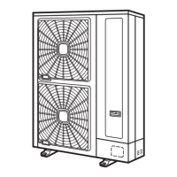
1. Electrical box.
2. Upper cover.
3. Refrigerant amount controller.
4. Pressure switch for control.
5. High pressure switch.
6. Blazing.
7. Discharge pipe.
¿ Opening electrical box (P plate)
1 Remove the service cover following Removing service cover, see on page 402 in this chapter.
2 Remove six (5) screws which fix the electrical box, and open the P plate turning counter clockwise approximately 90°.
• Check that the LED201 (red) on the inverter PCB (PCB2) is OFF when opening P-mounting plate.
1. P Plate.
2. Upper cover.
3. Screw.
4. Two (2) screws.
D A N G E R
• DO NOT touch electrical components while the LED201 (Red) is ON to avoid electrical shock. Wait until the LED
turns off.
¿ Removing four-way valve coil
1 Remove the service cover following Removing service cover, see on page 402.
2 Open the P plate following Opening electrical box (P plate), see on page 410.
3 Disconnect the PCN6 connector on the control PCB of the electrical box.
4 Remove one (1) fixing screw to remove the 4-way valve coil.

 Loading...


