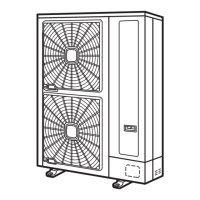
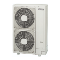
Wiring System [Connection (Connection of Terminals)]
Power Supply
DC inverter
[O.U.-O.U.(L1-L1, L2-L2, L3-L3, N-N)]
[I.U.-I.U.(L1-L1, N-N)]
Operating [O.U.-I.U., I.U.-I.U.(1-1, 2-2)]
Remote Control [I.U.-I.U.(A-A, B-B)]
N O T E
• O.U.: Outdoor Unit
• I.U.: Indoor Unit
3 Connect the wires between the outdoor unit and the indoor unit to the terminals 1 and 2 on the terminal board.
4 Do not run the wires in front of the fixing screw of the service access panel. If you do so, you will not be able to remove
the fixing screw.
1. Power wires.
2. Signal wires.
4.2.2 Setting the DIP switches for the outdoor unit
Quantity and position of DIP switches
The PCB1 (see the electrical wiring diagram - plane a) in the outdoor unit is operated with 6 types of dip switches, one
rotary switch and 3 types of push switch.

 Loading...


