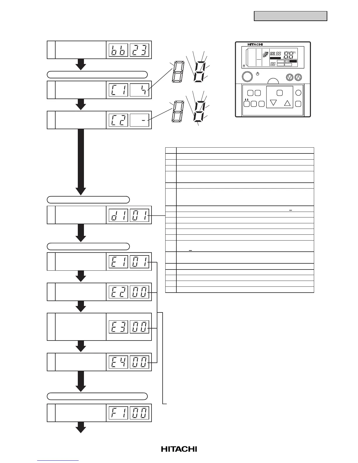
Indication on Micro-Computer Input/Output
Thermo Temp. of
Remote Control
Switch
11
Micro-Computer
Input/Output in
Outdoor Unit
13
Cause of Stoppage
14
Abnormality
Occurrence Times
15
Instantaneous Power
Failure Occurrence
Times in Indoor Unit
16
Abnormality
Occurrence Times
on Inverter
18
Transmission Error
Occurrence Times
between Remote
Control Switch and
Indoor Unit
17
Louver Sensor19
Micro-Computer
Input/Output in
Indoor Unit
12
Heating Thermo-ON
Cooling Thermo-ON
Dark
Alarm
Operation
H2
52H
to next page
Countable up to 99.
Over 99 times, "99" is always indicated.
(NOTE 1) If a transmitting error continues for 3 minutes, one
is added to the occurrence times.
(NOTE 2) The memorized data can be canceled by the
method indicated in 1.3.1 "Self-checking of PCBs
using Remote Control Switch" in pages 1-103, 104.
Symbols with a letter Y are relays on PCB
00 Operation OFF, Power OFF
01 Thermo-OFF (NOTE 1)
02 Alarm (NOTE 2)
03 Freeze Protection, Overheating Protection
05 Instantaneous Power Failure at Outdoor Unit, Reset
(NOTE 3)
06 Instantaneous Power Failure at Indoor Unit, Reset (NOTE 4)
07 Stoppage of Cooling Operation due to Low Outdoor Air
Temperature, Stoppage of Heating Operation due to
High Outdoor Air Temperature
08 Compressor Quantity Changeover, Stoppage (HP
>
8)
09 Demand of 4-Way Valve Changeover Stoppage (FX Only)
10 Demand, Enforced Stoppage
11 Retry due to Pressure Ratio Decrease
12 Retry due to Low Pressure Increase
13 Retry due to High Pressure Increase
14 Retry due to Abnormal Current of Constant Compressor
(HP
>
8)
15 Retry due to Abnormal High Temperature of Discharge
Gas, Excessively Low Suction Pressure
16 Retry due to Decrease of Discharge Gas Superheat
17 Retry due to Inverter Tripping
18 Retry due to Voltage Decrease
19 Expansion Valve Opening Change Protection
20 Operation Mode Changeover of Indoor Unit (NOTE 5)
(NOTE 1) Explanation of Term,
Thermo-ON: A condition that an indoor unit is
requesting compressor to operate.
Thermo-OFF: A condition that an indoor unit is not
requesting compressor to operate.
(NOTE 2) Even if stoppage is caused by "Alarm", "02" is not
always indicated.
(NOTE 3) If transmission between the inverter printed circuit board
and the control printed circuit board is not performed
during 30 seconds, the outdoor unit is stopped.
In this case, stoppage is d1-05 cause and the alarm
code "04" may be indicated.
(NOTE 4) If transmission between the indoor unit and the
outdoor unit is not performed during 3 minutes,
indoor units are stopped.
In this case, stoppage is d1-06 cause and the alarm
code "03" may be indicated.
(NOTE 5) In the FSG and FS3 system "20" will be indicated
at the difference mode between indoor units.
Indication of Unit Stoppage Cause
Abnormality Occurrence Counter
Indication of Automatic Louver Condition
Y52C2
Y212
Dark
Y211
Y52C1
Y20B
Y20A
Outdoor Fan
 Loading...