Fire Alarm Control Panel Compact
26 FB 798238.GB0 / 10.14
5.6.1 Hardware
3
hardware
1 location : not assigned
3
1
3
location
1 OUT_1
2 OUT_2
3 OUT_3
4 OUT_4
5 OUT_5
6 OUT_6
7 OUT_7
3
1
3
*hardware
1 location : OUT_1
3
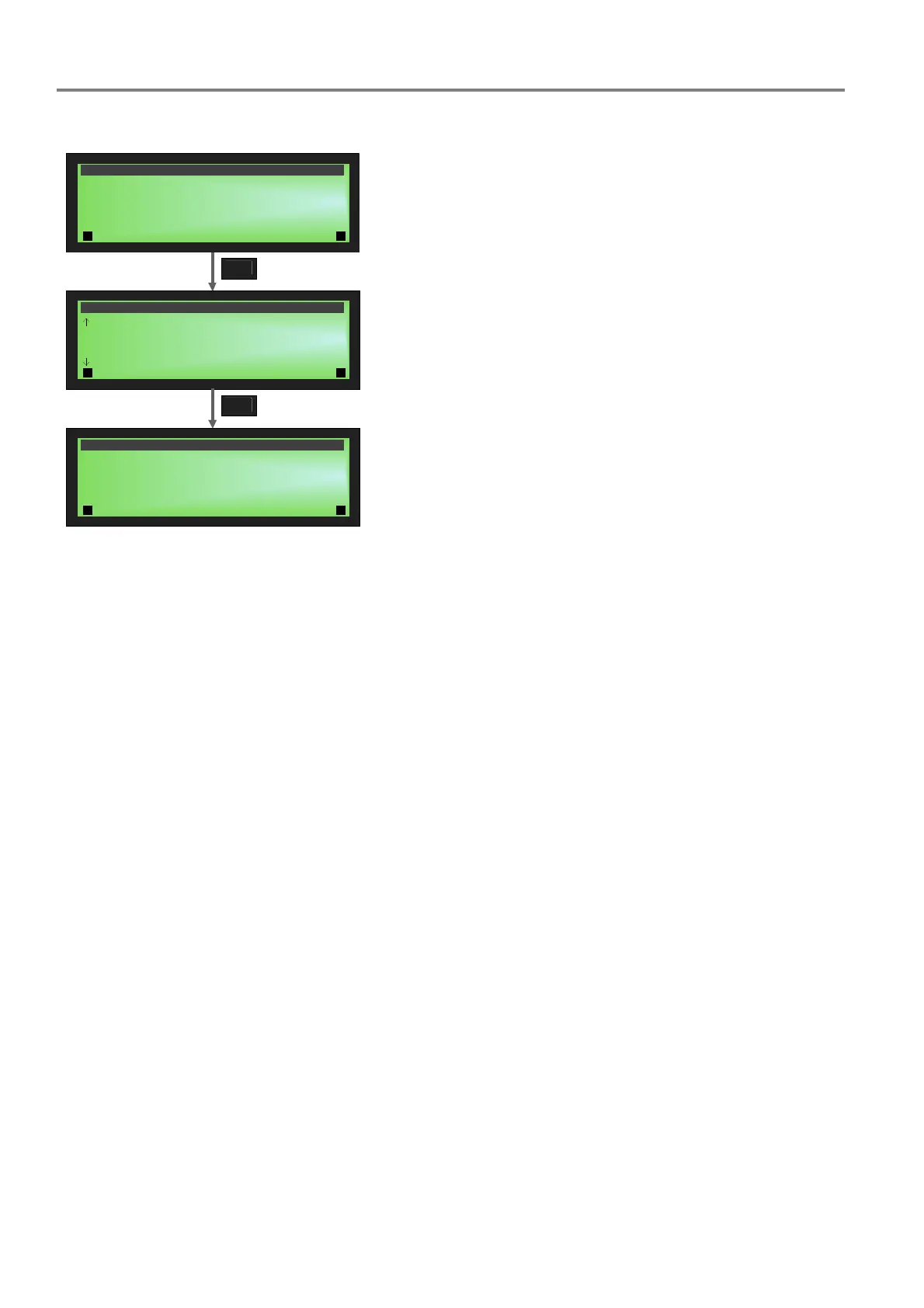
Fig. 38: >Hardware< menu screens
No hardware was programmed. Each control zone is usually
assigned one output. For example, OUT_1 is selected to trigger
the ATU.
Each HW output can only be assigned one control zone – the
plausibility check will otherwise show an error during data
saving.
The following monitored outputs can be selected:
OUT_1 - OUT_4 and the potential-free contacts
REL_1 - REL_5.

 Loading...