MPA2C3 Installation Guide 23
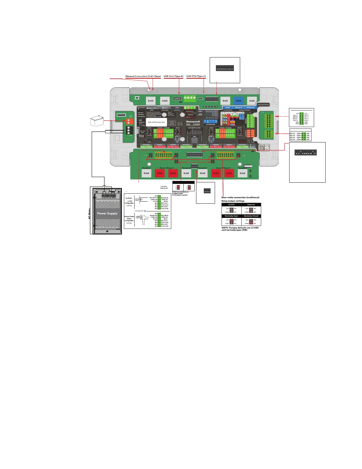
Figure 2-2 Access Control Panel Wiring and Components – Standard Metal Enclosure
Note: Maintain at least a 0.25 inch (0.65 cm) distance between the non-power limited
wiring (100-240 VAC, 50/60Hz input wiring, power line filter wiring, and battery
backup/charger wiring) and all other wiring, which is power-limited Class 2 wiring.
Warning: Do not plug in unknown USB devices (for example, USB Killers) which can damage
hardware components. This access control unit is not designed with a protective
function for any deliberately damaged USB devices. Honeywell is not responsible for
your losses caused by using deliberately damaged USB devices.
8 Auxiliary Inputs
4 Auxiliary Relay Outputs
OSDP Reader
PoE Switch
DIP Switch 3 (SW3)
OFF
12345678
ON
Set
1-4 OFF
5 EoL RS485 bus I/O Devices
6 EoL RS485 bus I/O Devices
7 EoL RS485 bus Downstream Panels
8 EoL RS485 bus Downstream Panels
10
14
12
16
11
9
13
15
5
6
7
8
Set
DIP Switch 1 (SW1)
OFF
12345678910
ON
1Wiegand READER 1(A/B)-OSDP
2 OFF
3 secondary /Primary panel(ON)
4 User IP address /Deafault IP address
5 Address 5
6 Address 4
7 Address 3
8 Address 2
9 Address 1(ON)
10 Wiegand READER 2(A/B)-OSDP2
Set
DIP Switch 2 (SW2)
OFF
1234
ON
1 EoL OSDP1
2 EoL OSDP1
3 EoL OSDP2
4 EoL OSDP2
OUT
READER V Extern
OUT
OUT
OUT
READER V Extern
Wiegand Reader
 Loading...


