MAN0984_Iss 4_01/19 Touchpoint Plus
Pt. No. 3011M5001 27 Technical Handbook
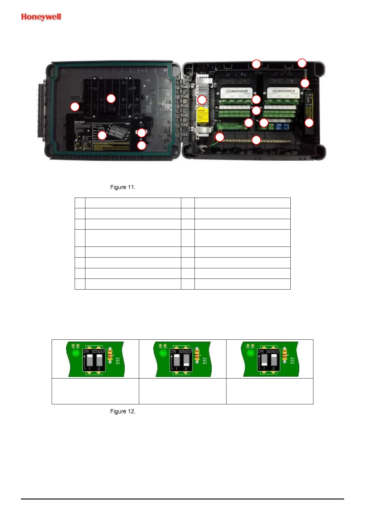
3.3.2 TPPL Expansion Unit
This figure shows the building blocks of the Touchpoint Plus Expansion Unit.
Expansion Unit Layout Before Installation
Main Module (Power and CAN
only)
Ethernet Connector not fitted
Input Module (Dual shown)
Switched Mode Power Supply
DIP Switch (on backplane)
3.3.3 TPPL DIP Switches
TPPL Backplanes have a DIP switch (item 7 in the figures above) that controls the interaction between the master
(basic) and the optional expansion unit backplanes. Once set these DIP switches need not be altered.
Basic Unit with Expansion
Unit
1 On, 2 Off
Expansion Unit
1 Off, 2 On
Backplane DIP Switch Settings

 Loading...


