Electrical Power Connection and Interfacing
MAN0984_Iss 4_01/19 Touchpoint Plus
Pt. No. 3011M5001 31 Technical Handbook
5.1.1 AC Power Supply
To confirm or alter the pre-set operating voltage, open the system front cover, locate the SMPS on the left side and, if
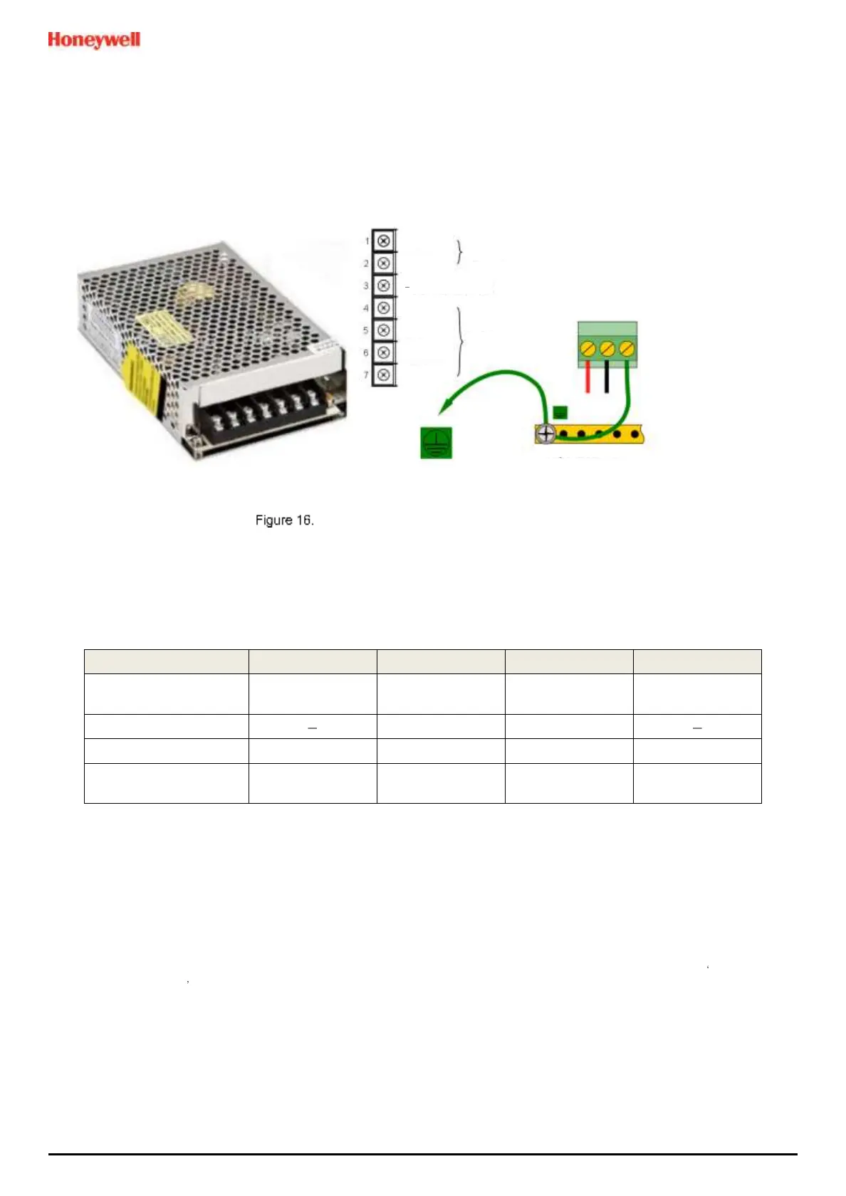
required, change the voltage selector using a screwdriver at the point shown at the top of the yellow and black label.
Switched Mode Power Supply (SMPS) Connections
Note: Mains Earth (Ground) must only be connected to the protective earth (ground) rail, and not to the SMPS.
Regional power cable wires are coloured in accordance with the following code:
Table 5. Regional Power Cable Colours
Before making any electrical connections or changes ensure that:
• the mains supply isolator switch is in the Off position
• the system is set up to operate at the correct voltage
Refer to Ch.3.2.1 Power Requirements for further information on system electrical specifications.
Note 1: Input voltage of less than DC 23.5 V will fail to charge the backup battery, and it will generate a Battery
unchargeable warning message.
Note 2: If Field detectors exceed 20 W per channel or a combined total of 40 W they may need their own power
supplies. Refer to Table 6: mA Input Module Connections for further information.
 Loading...


