Commissioning
MAN0984_Iss 4_01/19 Touchpoint Plus
Pt. No. 3011M5001 75 Technical Handbook
6.15 Calibrating Input Channels
6.15.1 Adjusting the mV Sensor Baseline
It is important to select [Adjust mV Baseline] when calibrating a new or replacement sensor for the first time, and
[Span] for all calibrations thereafter. This also applies when either the detector type or sensor type is changed during
channel configuration, even though the sensor itself remains the same.
To adjust the mV Sensor Baseline:
1) Replace the catalytic bead
2) Check the mV sensor wiring is undamaged and correctly connected.
3) Perform the next check under clean air.
4) Login as Administrator or Service.
5) Touch Menu>Maintenance>Adjust mV Baseline and select a mV input channel.
6) Touch [Start].
7) Check mV sensor type setting is correct.
8) Carry out the sensor calibration as shown in the next section (the mV input channel will be automatically
inhibited during this procedure).
6.15.2 Calibrating a mV Input Channel
It is important to select [First Calibration] when calibrating a new or replacement sensor for the first time.
To calibrate a mV input channel, follow the procedure below in combination with the relevant instructions in the
sensor manual.
This procedure requires 2 people in radio or telephone contact.
Only trained technicians are authorized to carry out sensor calibration.
Caution: Ensure that any relay operated devices (drenchers, repeater alarms, etc.) are inhibited before starting this
test.
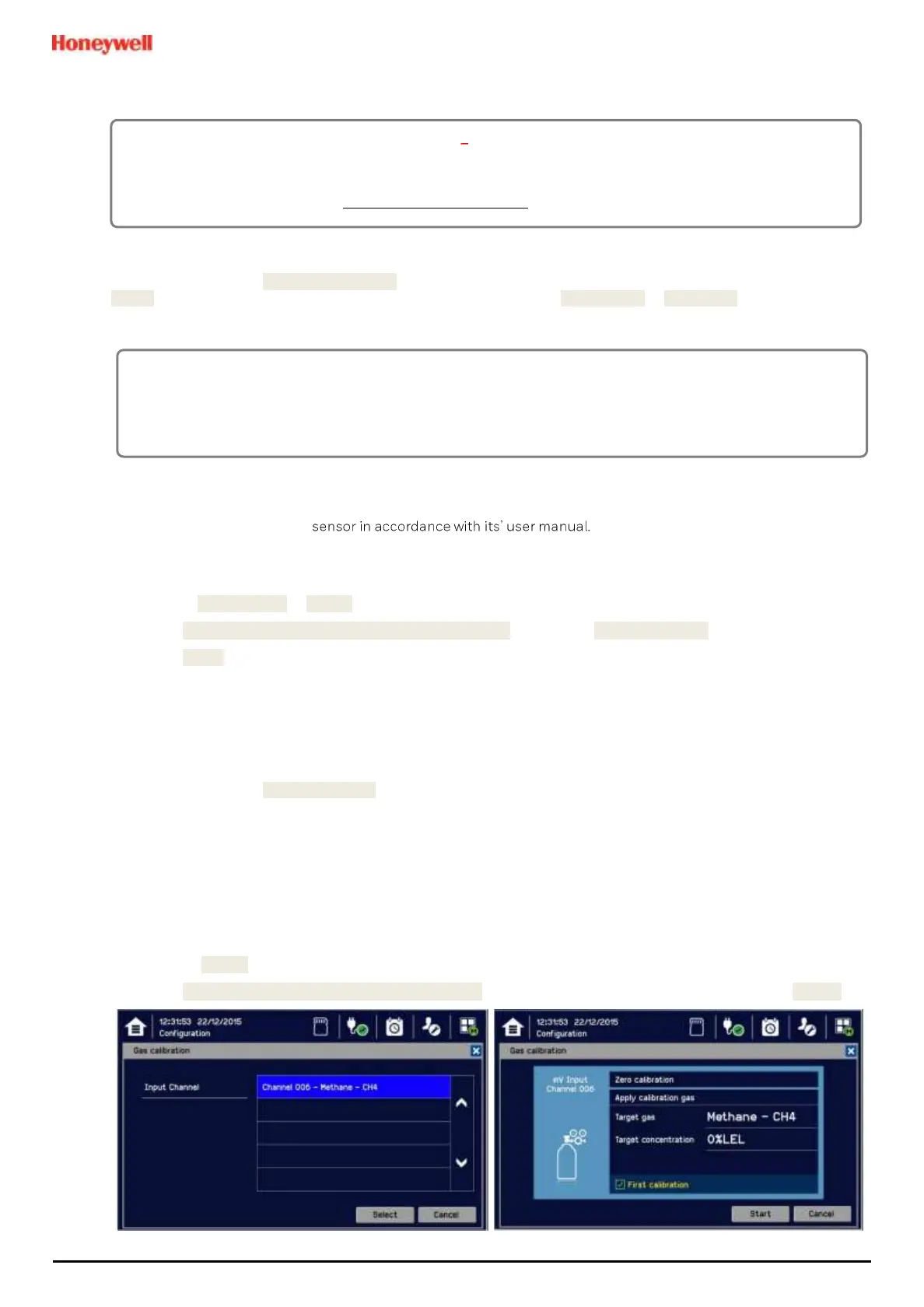
1) Log in as Service.
2) Touch Menu>Maintenance>Gas Calibration. Touch the channel to be calibrated followed by [Select].
CAUTION ALARM INHIBIT
For catalytic bead type detectors, the Analogue Input Modules form part of the measuring circuit. Therefore
all commissioned mV channels remain in Inhibit state until they are calibrated.
You should consider alternative safety measures when performing these procedures.

 Loading...


