Electrical Power Connection and Interfacing
MAN0984_Iss 4_01/19 Touchpoint Plus
Pt. No. 3011M5001 49 Technical Handbook
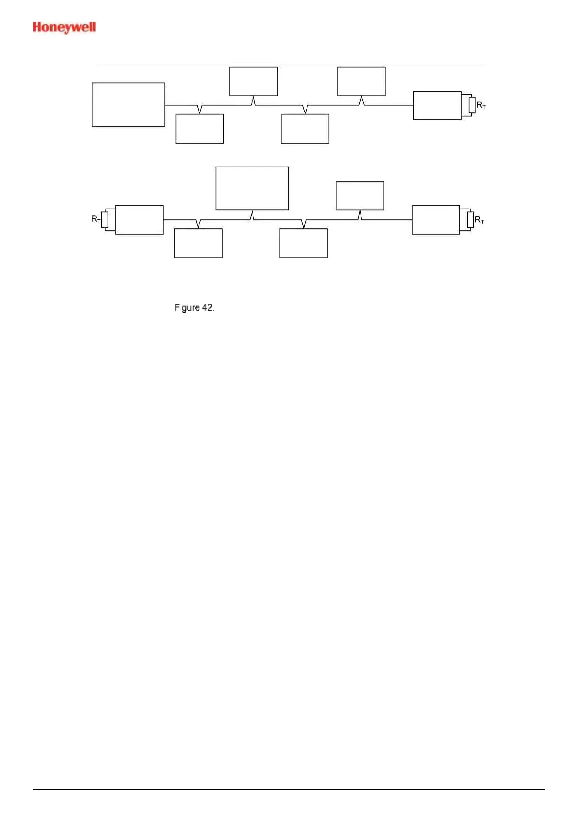
Two Modbus Installation Examples (other methods may be used)
Note: TPPL can fill any of the slave nodes, and it can support up to 32 nodes in Multi-Drop Mode (one master node
with 31 slave nodes).
5) Refit the PCB cover. Do not overtighten the screws.
6) Close and secure the enclosure door.
7) Switch on the backup and main power supplies and wait for the system to initialise.
8) Test the Modbus installation.
5.3.1 Modbus Configuration
For information on Modbus Configuration see Ch.6.12 Modbus RTU Settings.
 Loading...


