Electrical Power Connection and Interfacing
MAN0984_Iss 4_01/19 Touchpoint Plus
Pt. No. 3011M5001 48 Technical Handbook
2) Slide the cover off carefully and place it on a clean, anti-static surface.
3) Fit the Modbus PCB by carefully aligning the connectors and pushing down gently, observing the orientation
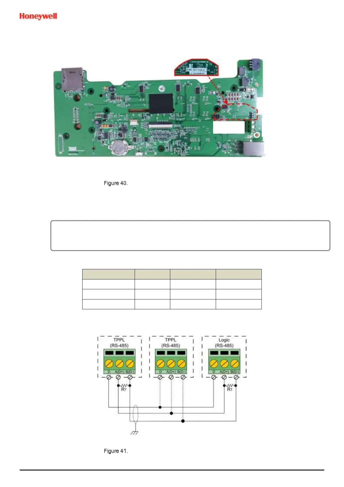
shown below:
Motherboard Showing the Modbus PCB Location
4) Connect the Modbus cables as shown below. (You should connect a 120Ω termination resistor (R
T
) between A and
B to prevent reflections on the RS485 circuit if TPPL is the last node in a Modbus system highway.)
Note: External R
T
is not needed if the logic solver side has an internal R
T
.
CAUTION
Some manufacturers have been known to incorrectly reverse their RS485 Data terminals, which can cause
Tx/Rx to fail. If this happens, simply swap over A and B cables and re-test.

 Loading...


