Touchpoint Plus User Guide
MAN0984_Iss 4_01/19 Touchpoint Plus
Pt. No. 3011M5001 81 Technical Handbook
Chapter 7.
The TPPL Touchscreen provides the primary means of control and viewing. Secondly, the Web Interface can be used
for remote viewing (see Ch.7.17 Monitoring TPPL via the Optional Web Interface).
7.1 User Interface General
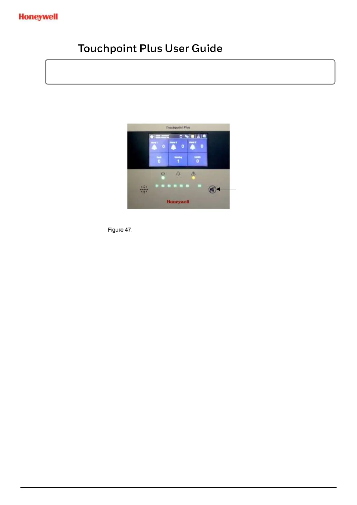
Touchpoint Plus Controller User Interface
The User Interface panel (shown above) has:
• A colour Touch screen for normal system operation, maintenance and configuration
• Power, Alarm / Fault and Inhibit state LEDs
• Active Channel (01 to 08) status indicators (Channel 07 is not commissioned in this example)
• Active Expansion Channel (09 to 16) status indicators (not commissioned above)
• Accept* / Reset membrane button (arrowed above)
• Integral Alarm Buzzer (Left side)
*The membrane button acknowledges and silences active alarms and resets latched alarms, depending on the
situation and how long it is pressed. See Ch.7.8 Responding to Alarms for further information.
Further System Interfaces consist of:
• Remote inhibit and remote reset terminals in the Main module
• One fixed relay and two configurable relays in the Main Module for System Failure, Alarm and Inhibit
• Three dedicated alarm outputs for visual and audio alarms
• An SD Card slot for data logging and firmware/software updates
• An optional expansion unit with optional dual input module (mV & mA)
• Optional remote Web Interface networking via RS485 port
• Optional remote Modbus TCP/IP via hard-wired terminal

 Loading...


