I
-
Channel Measurements
Making Channel Measurements
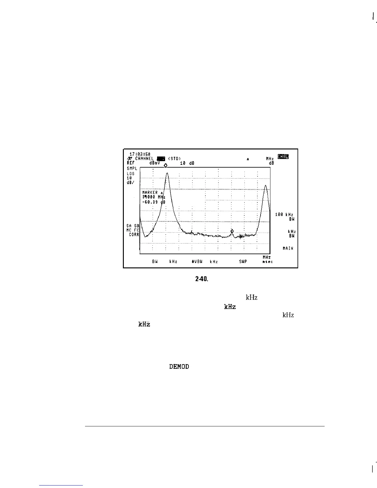
View ingress test
1. Select a channel, then press VIEW INGRESS A marker is placed on the
peak of the carrier, and the delta marker is activated.
2. After the displayed modulation and noise are reduced with minimum hold,
use the knob to position the delta marker on a signal appearing above the
noise. The frequency and amplitude differences between the peak carrier
level and the marker appear in the active function block. See Figure 2-40.
17:03:58
OEC 06, 1993
&
CHhNNEL
m
(910)
MKR a 3.000 FiHz
REF 36.8
dBmV
o
AT
10
dB
-60.39
dB
SflPL
:
:
:
CENTER 177.000 MHz
SPAN 6.008
IlHz
YRES
BW
100
kHr
WVBW
1
kHz
SWP
180
llscc
ml!
VIEW
CO-CHNL
LISTEN
AT MKR
108
kHz
RES
BW
30
kHz
RES
3W
MhIN
MENU
RT
Figure
2-40.
View Ingress
3. During the test, you can change the default 100
kHz
resolution bandwidth
(RBW). For example, you might select 30
kHz
RES BW to improve
resolution of signals close to the visual carrier. Return to 100
kHz
RBW by
selecting 100
kHz
RES BW
Selecting either resolution bandwidth resets the minimum hold function
used in the test to improve viewing of ingress.
4. Demodulate the ingress signal in AM or FM by pressing the
LISTEN AT MKR then
DEMOD
AM FM Press LISTEN OFF to return to
the previous menu.
5. Press VIEW CD-CHNL to set the analyzer to see co-channel interference.
See Figure 2-41.
Also, see Chapter 5 for more information about
VIEW CO-CHNL
2-60