Installation and Getting Started Guide
7 - 14
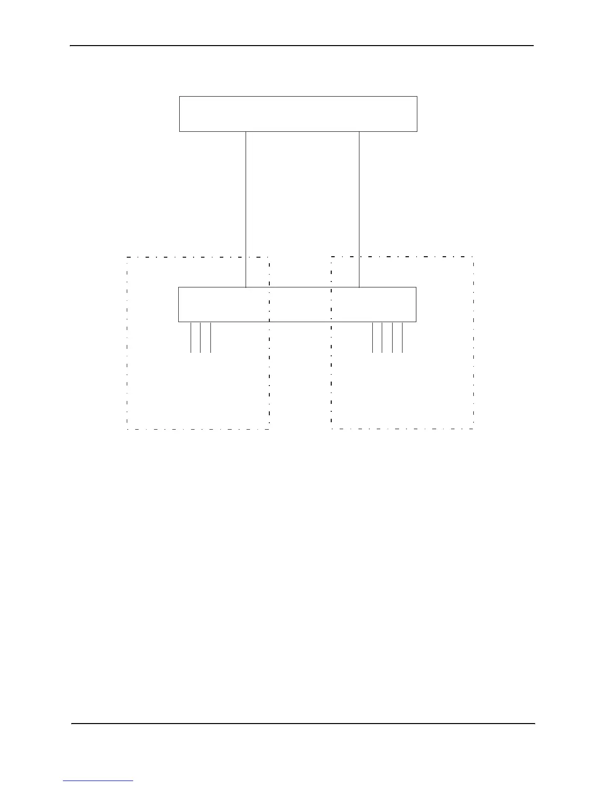
Figure 7.9 Port-based VLANs 222 and 333
To create the two port-based VLANs shown in Figure 7.9, use the following method.
USING THE CLI
HP9300(config)# vlan 222 by port
HP9300(config-vlan-222)# untag e 1/1 to 1/8
HP9300(config-vlan-222)# vlan 333 by port
HP9300(config-vlan-333)# untag e 1/9 to 1/16
Syntax:
vlan <vlan-id> by port
Syntax:
untagged ethernet <portnum> [to <portnum> | ethernet <portnum>]
EXAMPLE:
Figure 7.10 shows a more complex port-based VLAN configuration using multiple Routing Switches and IEEE
802.1q VLAN tagging. The backbone link connecting the three Routing Switches is tagged. One untagged port
within each port-based VLAN on 9308M-A connects each separate network wide Layer 2 broadcast domain to the
router for Layer 3 forwarding between broadcast domains. The STP priority is configured to force 9308M-A to be
the root bridge for VLANs RED and BLUE. The STP priority on 9308M-B is configured so that 9308M-B is the root
bridge for VLANs GREEN and BROWN.
Port 1/2
IP sub-net 2
IPX network 2
AppleTalk cable range 200
AppleTalk zone “CTP”
9308M
Ports 1/5 - 1/8
IP sub-net 2
IPX network 2
AppleTalk cable range 2
AppleTalk zone “CTP”
9308M
Port 1/1
IP sub-net 1
IPX network 1
AppleTalk cable range 100
AppleTalk zone “Prepress”
Layer port-based VLAN 333
Ports 1/5 - 1/8
Port 1/5
Layer port-based VLAN 222
Ports 1/1 - 1/4
Ports 1/2 - 1/4
IP sub-net 1
IPX network 1
AppleTalk cable range 100
AppleTalk zone “Prepress”
Port 1/1