Configuring Virtual LANs (VLANs)
7 - 15
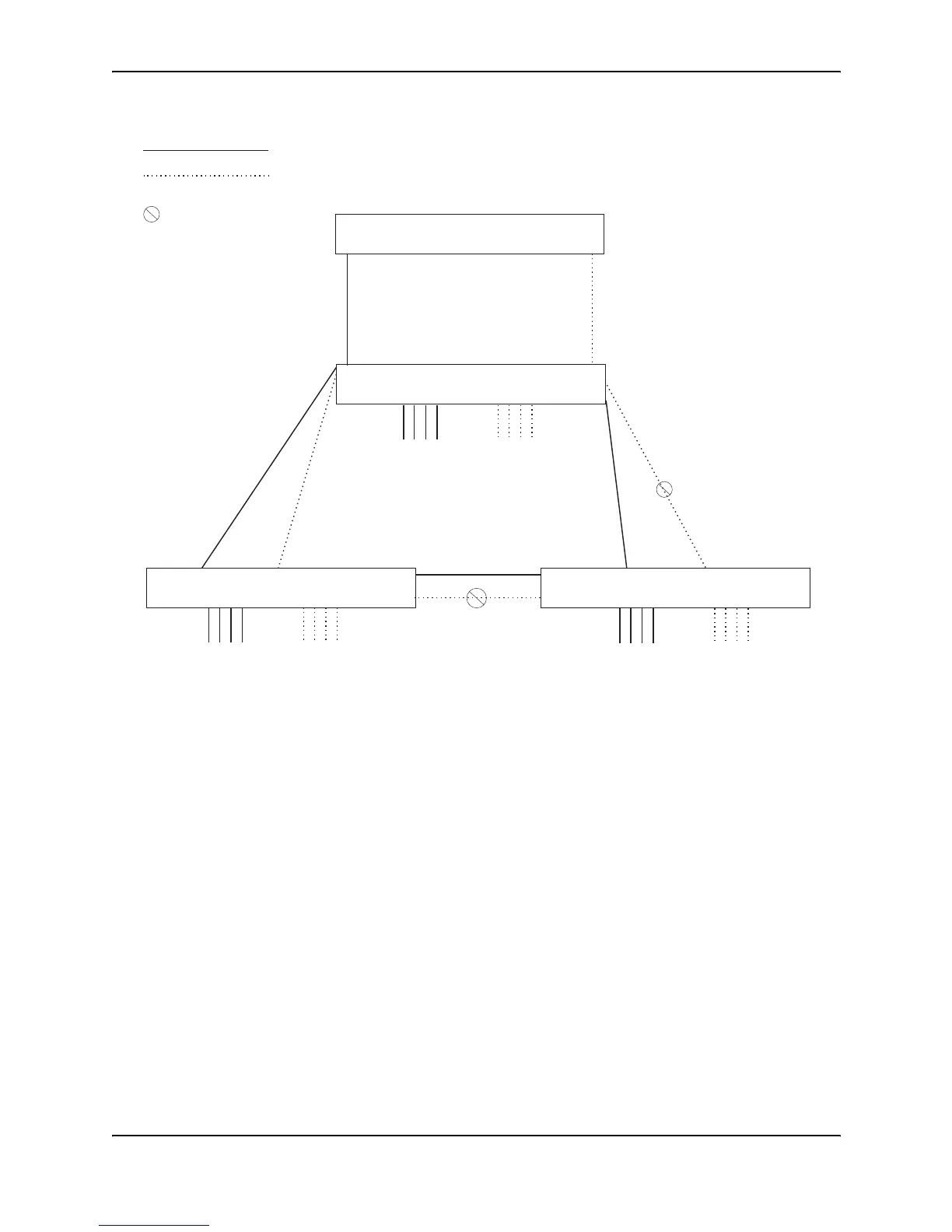
Figure 7.10 More complex port-based VLAN
To configure the Port-based VLANs on the HP 9308M Routing Switches in Figure 7.10, use the following method.
USING THE CLI
Configuring 9308M-A
Enter the following commands to configure 9308M-A:
HP9300> enable
HP9300# configure terminal
HP9300(config)# hostname HP9308-A
HP9308-A(config)# vlan 2 name BROWN
HP9308-A(config-vlan-2)# untag ethernet 1/1 to 1/4 ethernet 1/17
HP9308-A(config-vlan-2)# tag ethernet 1/25 to 1/26
HP9308-A(config-vlan-2)# spanning-tree
HP9308-A(config-vlan-2)# vlan 3 name GREEN
HP9308-A(config-vlan-3)# untag ethernet 1/5 to 1/8 ethernet 1/18
HP9308-A(config-vlan-3)# tag ethernet 1/25 to 1/26
HP9308-A(config-vlan-3)# spanning-tree
HP9308-A(config-vlan-3)# vlan 4 name BLUE
HP9308-A(config-vlan-4)# untag ethernet 1/9 to 1/12 ethernet 1/19
HP9308-A(config-vlan-4)# tag ethernet 1/25 to 1/26
HP9308-A(config-vlan-4)# spanning-tree
9308M-C
IP sub-net 2
IPX network 2
Atalk 200.1
Zone “B”
port 1/5
IP sub-net 1
IPX network 1
Atalk 100.1
Zone “A”
9308M-A
VLAN 3
“GREEN”
Ports 1/6 - 1/8
IP sub 2
IPX net 2
Atalk 200
Zone “B”
VLAN 2
“BROWN”
Ports 1/1 - 1/3
IP sub 1
IPX net 1
Atalk 100
Zone “A”
9308M-B
9304M
Root Bridge for
VLAN “BROWN”
Root Bridge for
VLAN “GREEN”
port 1/4
= STP blocked VLAN
VLAN “BROWN”
VLAN “GREEN”
VLAN 3
“GREEN”
Ports 1/6 - 1/8
IP sub 2
IPX net 2
Atalk 200
Zone “B”
VLAN 2
“BROWN”
Ports 1/1 - 1/3
IP sub 1
IPX net 1
Atalk 100
Zone “A”
VLAN 3
“GREEN”
Ports 1/6 - 1/8
IP sub 2
IPX net 2
Atalk 200
Zone “B”
VLAN 2
“BROWN”
Ports 1/1 - 1/3
IP sub 1
IPX net 1
Atalk 100
Zone “A”