Basic concepts in MSTP
Figure 14 Basic concepts in MSTP
MST region 1
MST region 2 MST region 3
MST region 4
VLAN 1 MSTI 1
VLAN 2
MSTI 2
Other VLANs
MSTI 0
VLAN 1 MSTI 1
VLAN 2
MSTI 2
Other VLANs
MSTI 0
VLAN 1 MSTI 1
VLAN 2
MSTI 2
Other VLANs
MSTI 0
VLAN 1 MSTI 1
VLAN 2&3
MSTI 2
Other VLANs
MSTI 0
CST
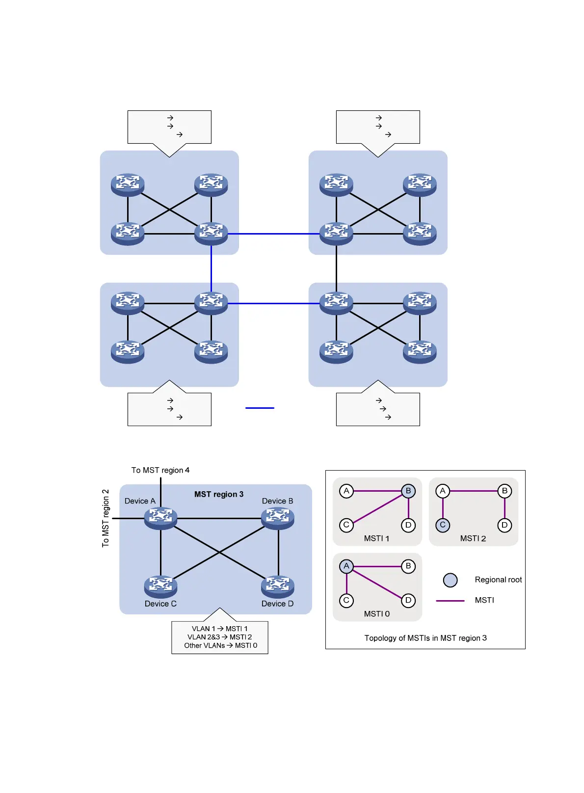
Figure 15 Network diagram and topology of MST region 3
As shown in Figure 14, a switched network comprises four MST regions, and each MST region comprises
four devices running MSTP. Figure 15 shows the networking topology of MST region 3.
55

 Loading...


