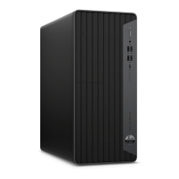
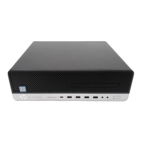
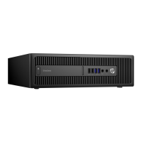
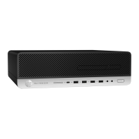
Front I/O and power switch assembly
The front I/O and power switch assembly is attached to the front of the chassis with one screw. Pull the
assembly away from the front of the chassis to remove.
1. Prepare the computer for disassembly (Preparation for disassembly on page 19).
2. Remove the computer access panel (Access panel on page 20).
3. Remove the front bezel (Front bezel on page 21).
4. Remove the drive cage (Drive cage on page 28).
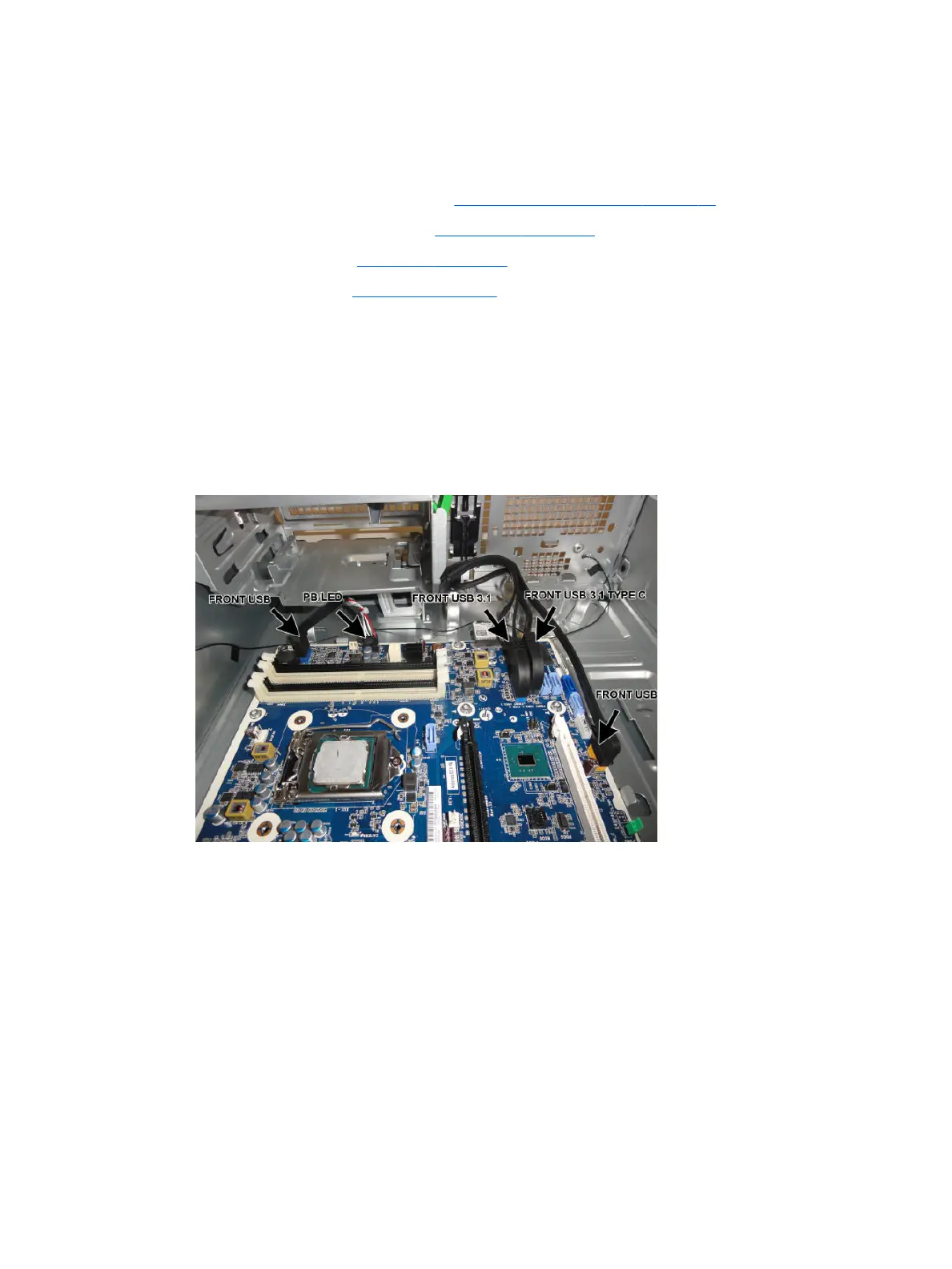
5. From the inside of the computer, disconnect the cables from the following system board connectors:
●
FRONT USB (blue connector)
●
PB/LED (black connector)
●
FRONT USB 3.1 (blue connector)
●
FRONT USB 3.1 TYPE C (black connector)
●
FRONT USB (yellow connector)
Front I/O and power switch assembly 55
 Loading...