EN
Separating the Engine Module from the Paper Feed Module
6-45
Facing the front of the engine module:
3. Remove 7 screws (shown in Figure 6-41 on page 6-44):
• 4 black, self-tapping M4 screws (3 in front and 1 in the right
rear)
• From the left rear, 3 M3 screws (1 recessed)
4. Disconnect the spring on the right side from the notch.
5. Disconnect the power switch rod.
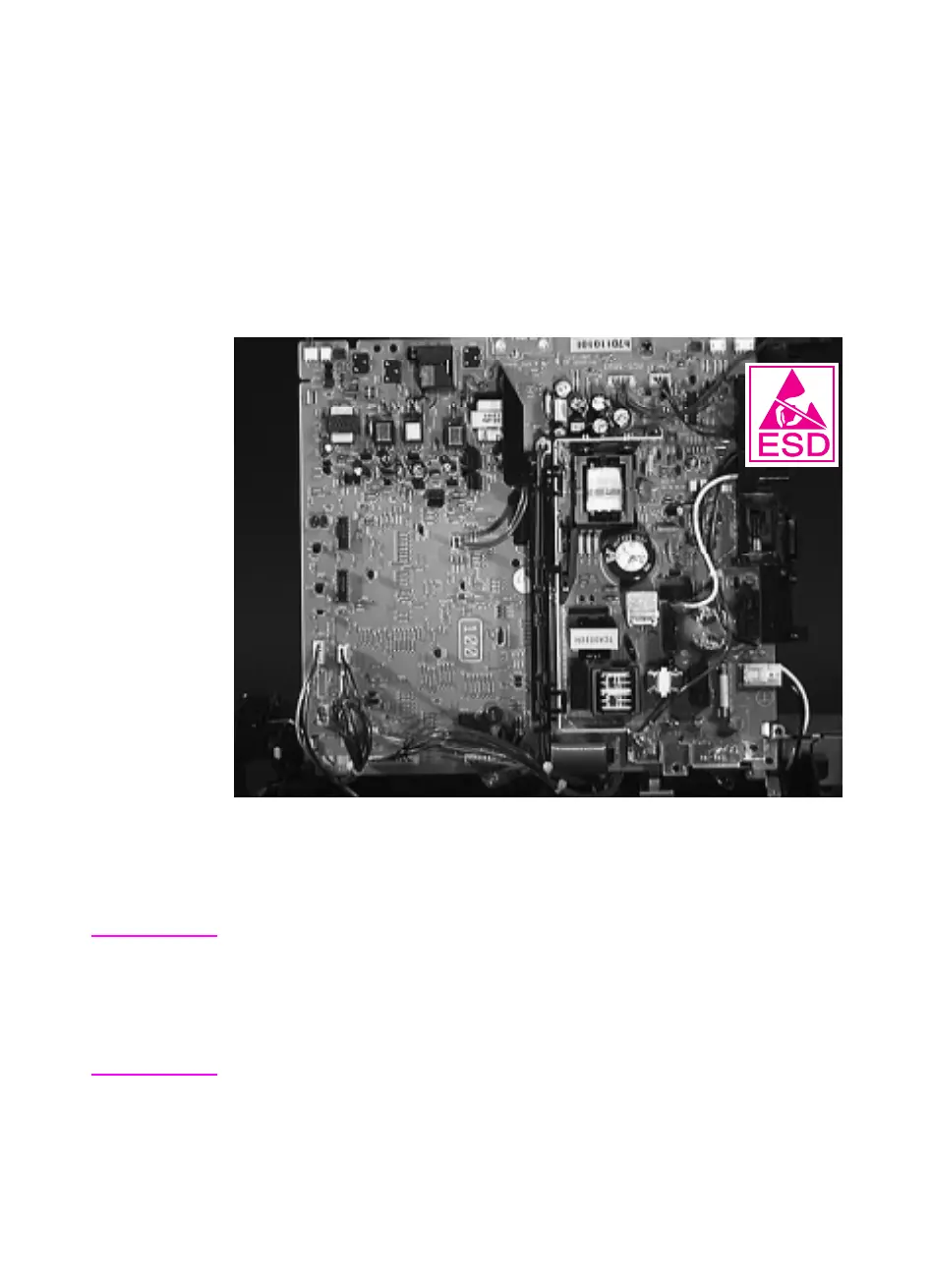
Figure 6-42
Removing the Engine Controller Board
6. Lifting from the printer’s left side (the side the Fan is on), tip the
board up, then unplug all connectors.
Hint
The black cable router in the middle of the Engine Controller Board can
be folded aside with the cables intact. When you replace the board,
reconnect and route all cables before reconnecting the power switch
rod.
Be sure to reconnect the spring on the right side to the ground plate.
 Loading...