5-6 Functional Information
EN
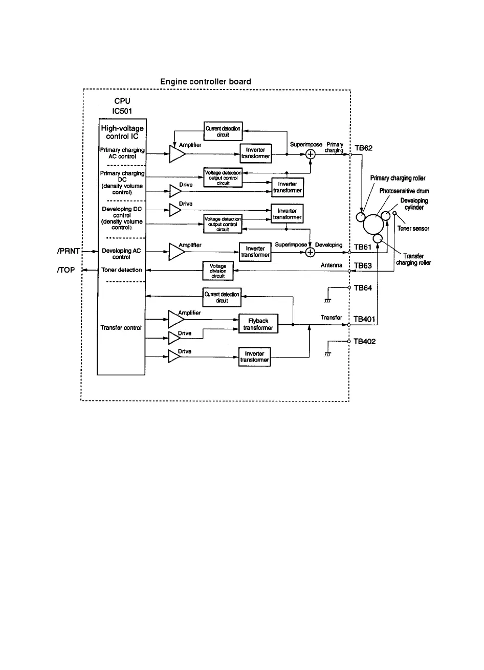
High Voltage Power Distribution
Figure 5-3 Engine Controller Board
In response to the instructions from the microprocessor
(CPU:IC 1501) on the Engine Controller Board, this circuit applies the
superimposed voltage of DC voltage and AC voltage to the primary
charging roller and developing cylinder, and a positive or negative DC
voltage to the transfer charging roller.
According to the image density information sent from the Formatter,
this circuit varies the primary DC bias and developing DC bias to
adjust the image density.
 Loading...