227
127.255.255.255/32 Direct 0 0 127.0.0.1 InLoop0
224.0.0.0/4 Direct 0 0 0.0.0.0 NULL0
224.0.0.0/24 Direct 0 0 0.0.0.0 NULL0
255.255.255.255/32 Direct 0 0 127.0.0.1 InLoop0
The output shows that PE 1 has a route to the remote CE. Output on PE 2 is similar.
# Verify that CEs of the same VPN can ping each other, whereas those of different VPNs cannot. For
example, CE 1 can ping CE 3 (10.3.1.1) but cannot ping CE 4 (10.4.1.1). (Details not shown.)
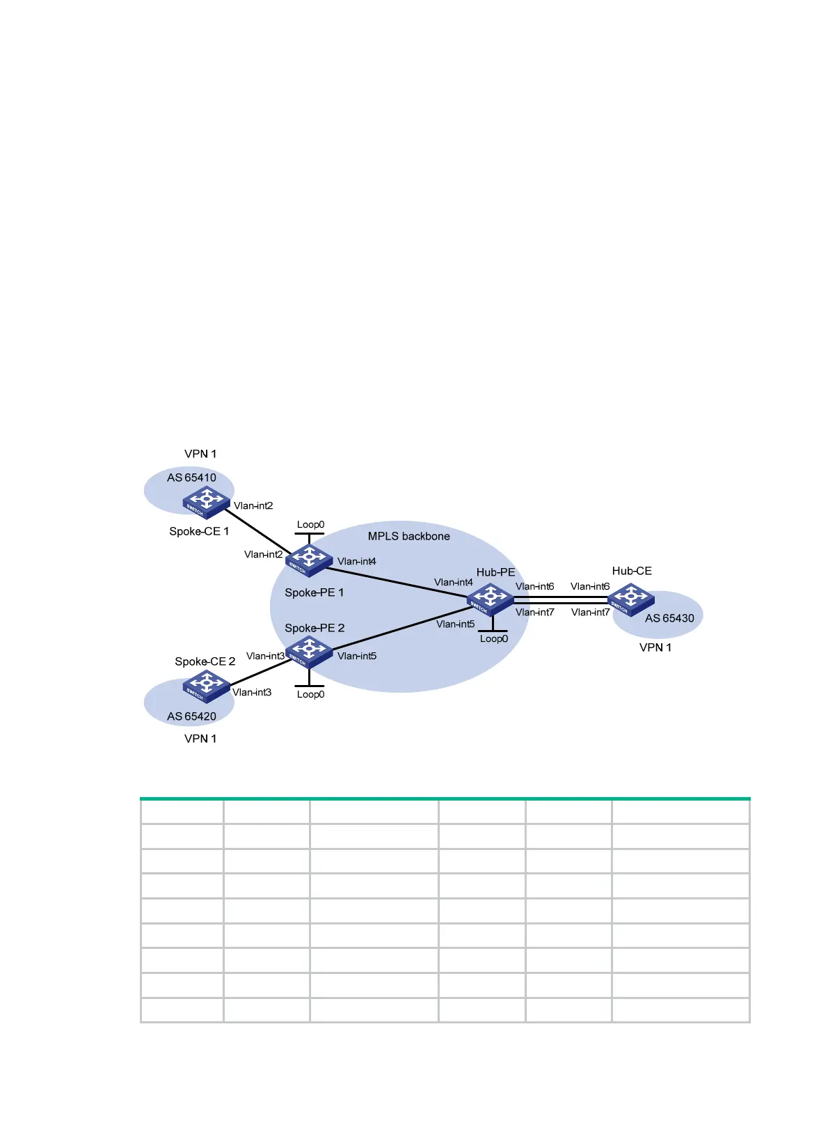
246BConfiguring a hub-spoke network
477BNetwork requirements
The Spoke-CEs cannot communicate directly. They can communicate only through Hub-CE.
Configure EBGP between the Spoke-CEs and Spoke-PEs and between Hub-CE and Hub-PE to
exchange VPN routing information.
Configure OSPF between the Spoke-PEs and Hub-PE to implement communication between the
PEs, and configure MP-IBGP between them to exchange VPN routing information.
Figure 67 Network diagram
Table 13 Interface and IP address assignment
Device Interface IP address Device Interface IP address
Spoke-CE 1 Vlan-int2 10.1.1.1/24 Hub-CE Vlan-int6 10.3.1.1/24
Spoke-PE 1 Loop0 1.1.1.9/32 Vlan-int7 10.4.1.1/24
Vlan-int2 10.1.1.2/24 Hub-PE Loop0 2.2.2.9/32
Vlan-int4 172.1.1.1/24 Vlan-int4 172.1.1.2/24
Spoke-CE 2 Vlan-int3 10.2.1.1/24 Vlan-int5 172.2.1.2/24
Spoke-PE 2 Loop0 3.3.3.9/32 Vlan-int6 10.3.1.2/24
Vlan-int3 10.2.1.2/24 Vlan-int7 10.4.1.2/24
Vlan-int5 172.2.1.1/24

 Loading...


