126
Destination : 30.1.1.1
FEC : 30.1.1.1
Protocol : Local
LSR Type : Ingress
Service : -
NHLFE ID : 1024
State : Active
Nexthop : 30.1.1.1
Out-Interface: Vlan1
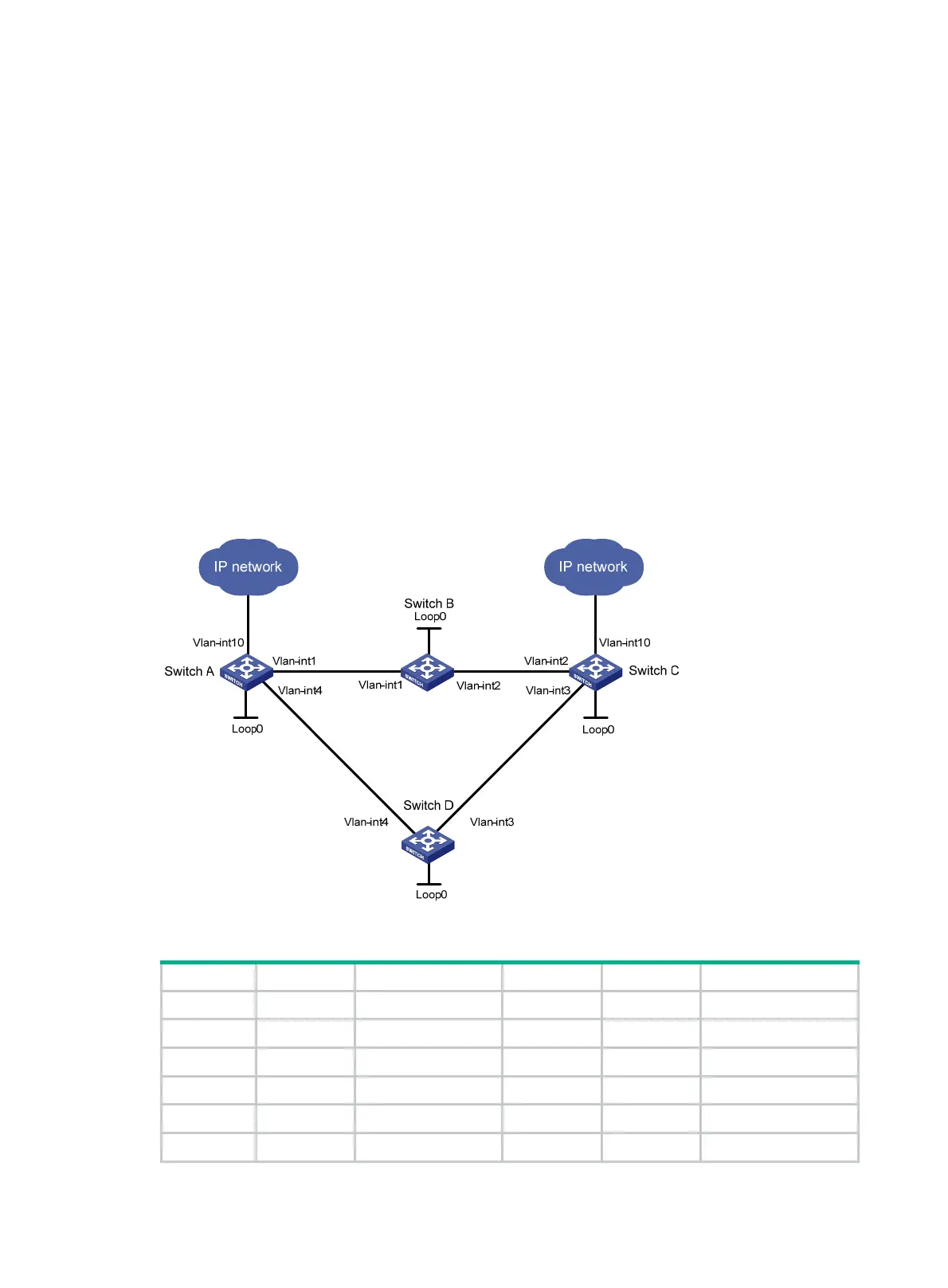
201BCRLSP backup configuration example
415BNetwork requirements
Switch A, Switch B, Switch C, and Switch D run IS-IS and IS-IS TE.
Use RSVP-TE to establish an MPLS TE tunnel from Switch A to Switch C to transmit data between
the two IP networks. Enable CRLSP hot backup for the tunnel to simultaneously establish a primary
CRLSP and a backup CRLSP. When the primary CRLSP fails, traffic is switched to the backup
CRLSP.
Figure 35 Network diagram
Table 6 Interface and IP address assignment
Device Interface IP address Device Interface IP address
Switch A Loop0 1.1.1.9/32 Switch D
Loop0
4.4.4.9/32
Vlan-int1 10.1.1.1/24 Vlan-int4 30.1.1.2/24
Vlan-int4 30.1.1.1/24 Vlan-int3 40.1.1.1/24
Vlan-int10 100.1.1.1/24 Switch C Loop0 3.3.3.9/32
Switch B Loop0 2.2.2.9/32
Vlan-int2
20.1.1.2/24
Vlan-int1 10.1.1.2/24 Vlan-int3 40.1.1.2/24

 Loading...


