258
251BConfiguring MPLS L3VPN carrier's carrier in different ASs
492BNetwork requirements
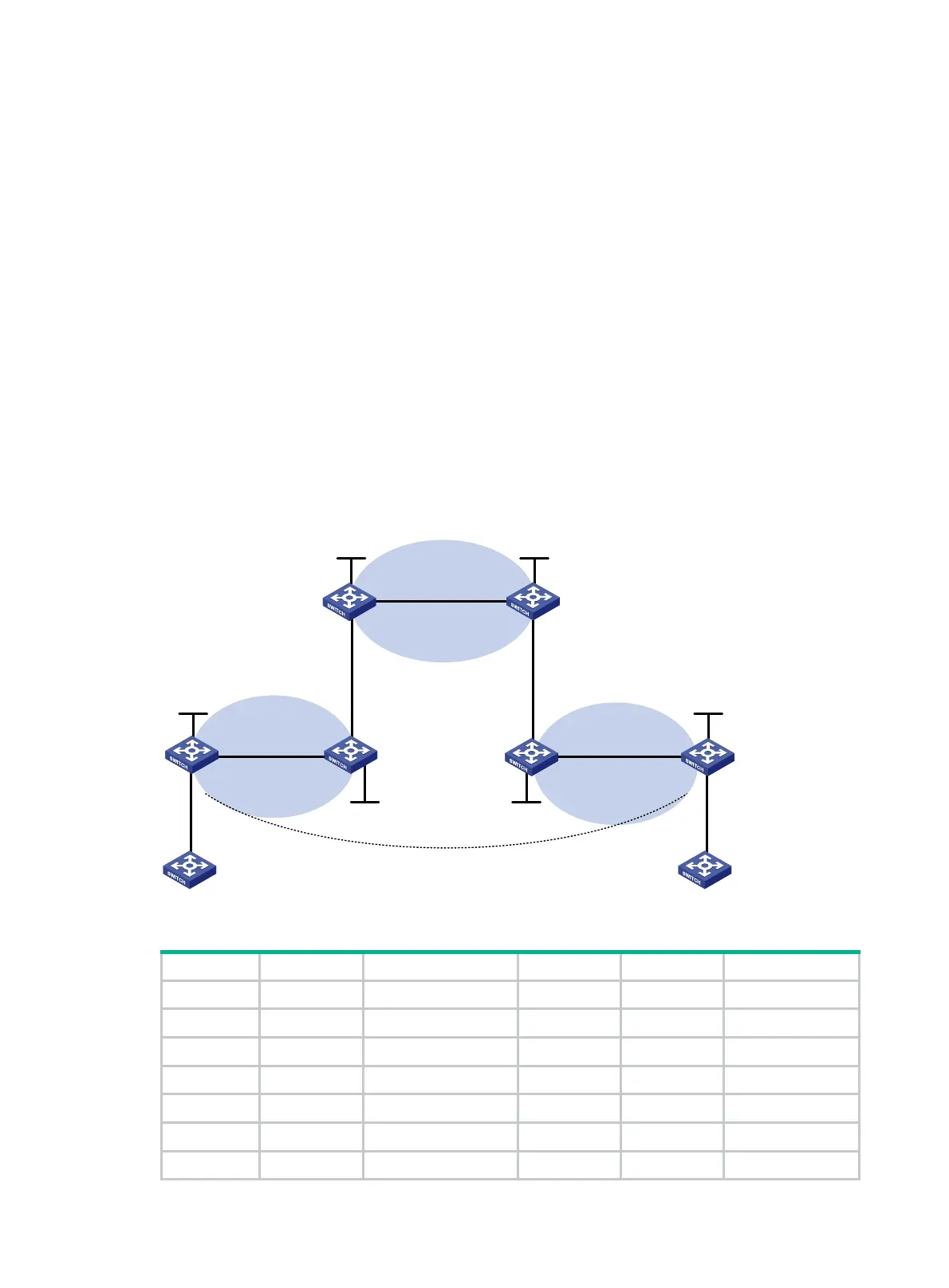
Configure carrier's carrier for the scenario shown in 810HFigure 72. In this scenario:
• PE 1 and PE 2 are the provider carrier's PE switches. They provide VPN services for the
customer carrier.
• CE 1 and CE 2 are the customer carrier's switches. They are connected to the provider carrier's
backbone as CE switches.
• PE 3 and PE 4 are the customer carrier's PE switches. They provide MPLS L3VPN services for
the end customers.
• CE 3 and CE 4 are customers of the customer carrier.
• The customer carrier and the provider carrier reside in different ASs.
The key to carrier's carrier deployment is to configure exchange of two kinds of routes:
• Exchange of the customer carrier's internal routes on the provider carrier's backbone.
• Exchange of the end customers' VPN routes between PE 3 and PE 4, the PEs of the customer
carrier. In this process, an MP-EBGP peer relationship must be established between PE 3 and
PE 4.
Figure 72 Network diagram
Table 18 Interface and IP address assignment
Device Interface IP address Device Interface IP address
CE 3 Vlan-int11 100.1.1.1/24 CE 4 Vlan-int11 120.1.1.1/24
PE 3 Loop0 1.1.1.9/32 PE 4 Loop0 6.6.6.9/32
Vlan-int11 100.1.1.2/24 Vlan-int11 120.1.1.2/24
Vlan-int12 10.1.1.1/24 Vlan-int12 20.1.1.2/24
CE 1 Loop0 2.2.2.9/32 CE 2 Loop0 5.5.5.9/32
Vlan-int12 10.1.1.2/24 Vlan-int11 21.1.1.2/24
Vlan-int11 11.1.1.1/24 Vlan-int12 20.1.1.1/24
PE 1
PE 2
Provider carrier
Customer carrier
PE 4
CE 2CE 1
PE 3
CE 3
CE 4
AS 65410 AS 65420
Loop0 Loop0
Loop0
Customer carrier
Vlan-int11
Loop0
Loop0
AS 100 AS 100
Vlan-int11
Vlan-int12
Vlan-int12
Vlan-int11
Vlan-int11
Vlan-int12
Vlan-int12
Vlan-int11
Vlan-int11
Vlan-int12
Vlan-int12
Vlan-int11
Vlan-int11
MP-EBGP
AS 100
AS 200
AS 300

 Loading...


