329
56 bytes from 12::1, icmp_seq=3 hlim=59 time=1.000 ms
56 bytes from 12::1, icmp_seq=4 hlim=59 time=0.000 ms
--- Ping6 statistics for 12::1 ---
5 packet(s) transmitted, 5 packet(s) received, 0.0% packet loss
round-trip min/avg/max/std-dev = 0.000/0.400/1.000/0.490 ms
276BConfiguring IPv6 MPLS L3VPN inter-AS option A
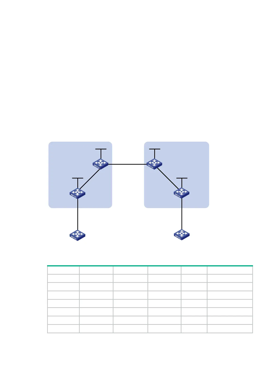
537BNetwork requirements
CE 1 and CE 2 belong to the same VPN. CE 1 accesses the network through PE 1 in AS 100, and
CE 2 accesses the network through PE 2 in AS 200.
Configure IPv6 MPLS L3VPN inter-AS option A, and use the VRF-to-VRF method to manage VPN
routes.
Run OSPF on the MPLS backbone of each AS.
Figure 85 Network diagram
Table 29 Interface and IP address assignment
Device Interface IP address Device Interface IP address
CE 1 Vlan-int12 2001:1::1/96 CE 2 Vlan-int12 2001:2::1/96
PE 1 Loop0 1.1.1.9/32 PE 2 Loop0 4.4.4.9/32
Vlan-int12 2001:1::2/96 Vlan-int12 2001:2::2/96
Vlan-int11 172.1.1.2/24 Vlan-int11 162.1.1.2/24
ASBR-PE 1 Loop0 2.2.2.9/32 ASBR-PE 2 Loop0 3.3.3.9/32
Vlan-int11 172.1.1.1/24 Vlan-int11 162.1.1.1/24
Vlan-int12 2002:1::1/96 Vlan-int12 2002:1::2/96
Loop0 Loop0
Loop0 Loop0
Vlan-int12
CE 1 CE 2
AS 65001 AS 65002
PE 1
PE 2
ASBR-PE 2
ASBR-PE 1
MPLS backbone
MPLS backbone
AS 100
AS 200
Vlan-int12
Vlan-int12
Vlan-int12
Vlan-int11
Vlan-int11
Vlan-int12Vlan-int12
Vlan-int11
Vlan-int11

 Loading...


