50
100 bytes from 10.1.1.1: Sequence=5 time=1 ms
--- FEC: 11.1.1.0/24 ping statistics ---
5 packets transmitted, 5 packets received, 0.0% packet loss
round-trip min/avg/max = 1/1/1 ms
52B
IPv6 LDP configuration examples
161BIPv6 LDP LSP configuration example
355BNetwork requirements
Switch A, Switch B, and Switch C all support MPLS.
Configure LDP to establish IPv6 LSPs between Switch A and Switch C, so subnets 11::0/64 and
21::0/64 can reach each other over MPLS.
Configure LDP to establish IPv6 LSPs only for destinations 100::1/128, 100::2/128, 100::3/128,
11::0/64, and 21::0/64 on Switch A, Switch B, and Switch C.
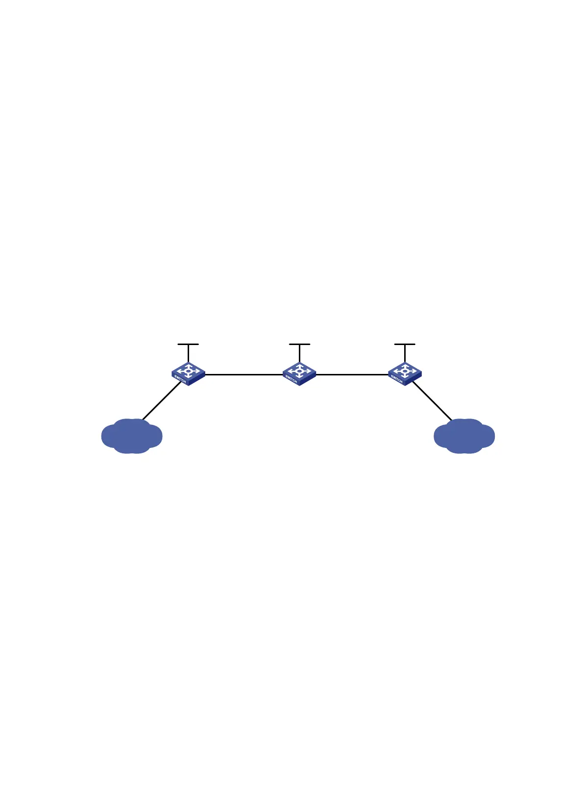
Figure 20 Network diagram
356BRequirements analysis
• To ensure that the LSRs establish IPv6 LSPs automatically, enable IPv6 LDP on each LSR.
• To establish IPv6 LDP LSPs, configure an IPv6 routing protocol to ensure IP connectivity
between the LSRs. This example uses OSPFv3.
• To control the number of IPv6 LSPs, configure an IPv6 LSP generation policy on each LSR.
357BConfiguration procedure
1. Configure IPv6 addresses and masks for interfaces, including the loopback interfaces, as
shown in
700HFigure 20. (Details not shown.)
2. Configure OSPFv3 on each switch to ensure IP connectivity between them:
# Configure Switch A.
<SwitchA> system-view
[SwitchA] ospfv3
[SwitchA-ospfv3-1] router-id 1.1.1.9
[SwitchA-ospfv3-1] area 0
[SwitchA-ospfv3-1-area-0.0.0.0] quit
[SwitchA-ospfv3-1] quit
[SwitchA] interface loopback 0
Loop0
2.2.2.9/32
100::2/128
Vlan-int3
20::1/64
Loop0
3.3.3.9/32
100::3/128
Loop0
1.1.1.9/32
100::1/128
Vlan-int2
10::1/64
Vlan-int2
10::2/64
Vlan-int3
20::2/64
Switch A Switch B Switch C
11::0/64 21::0/64
Vlan-int4
11::1/64
Vlan-int5
21::1/64

 Loading...


