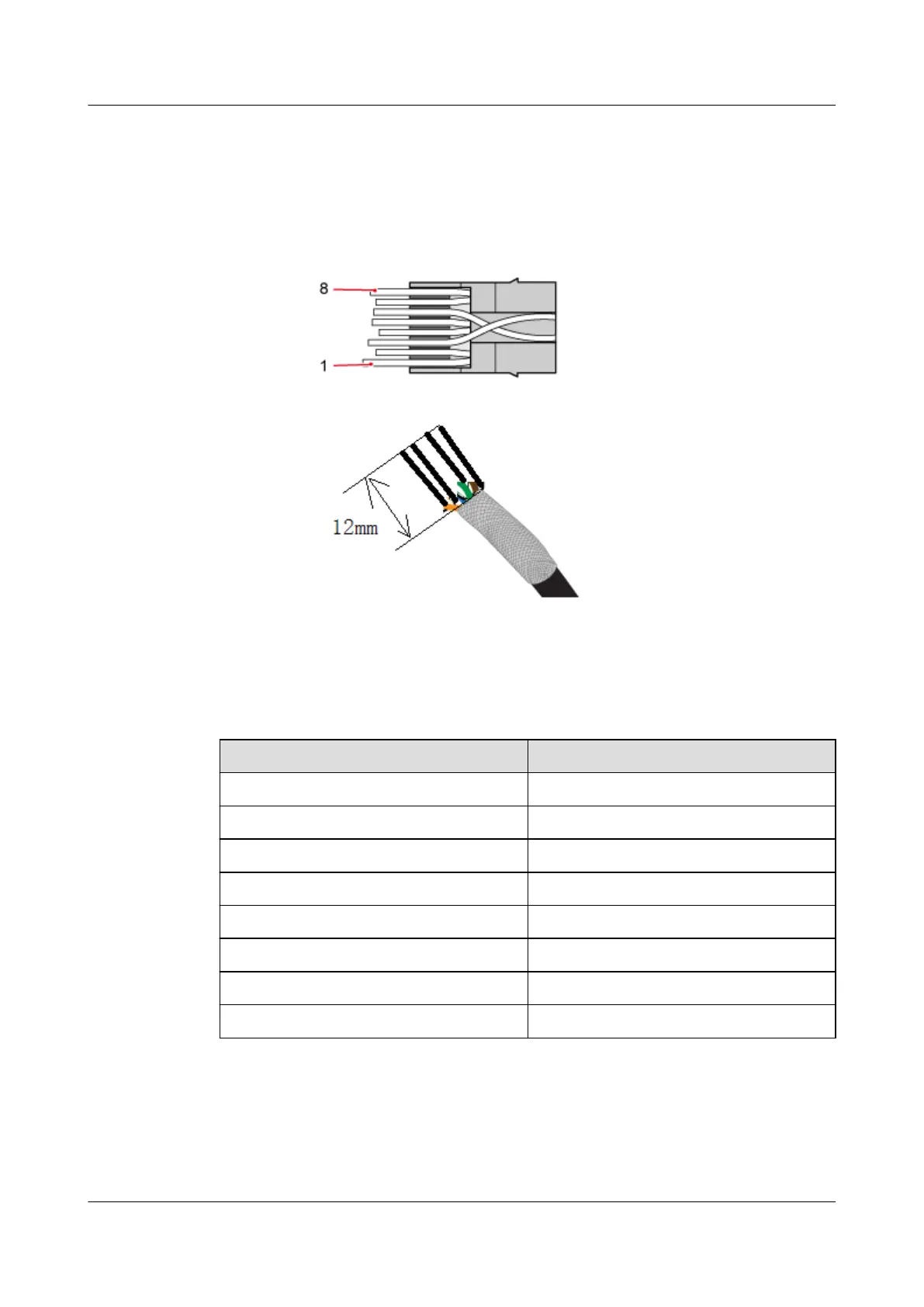
Step 2 Arrange the twisted pair wires in the order of colors shown in Table 5-8 and cut the wire ends
neatly with 12 mm core wires left, as shown in Figure 5-59.
Figure 5-59 Core wire order
Table 5-8 Mapping between core wires and pins
Pin ID
Core Wire Color
1 White-orange
2 Orange
3 White-green
4 Blue
5 White-blue
6 Green
7 White-brown
8 Brown
Step 3 Route the arranged core wires through the RJ45 connector, as shown in Figure 5-60.
AP4050DN-E
Hardware Installation and Maintenance Guide
5 Appendix
Issue 05 (2018-02-02) Huawei Proprietary and Confidential
Copyright © Huawei Technologies Co., Ltd.
68