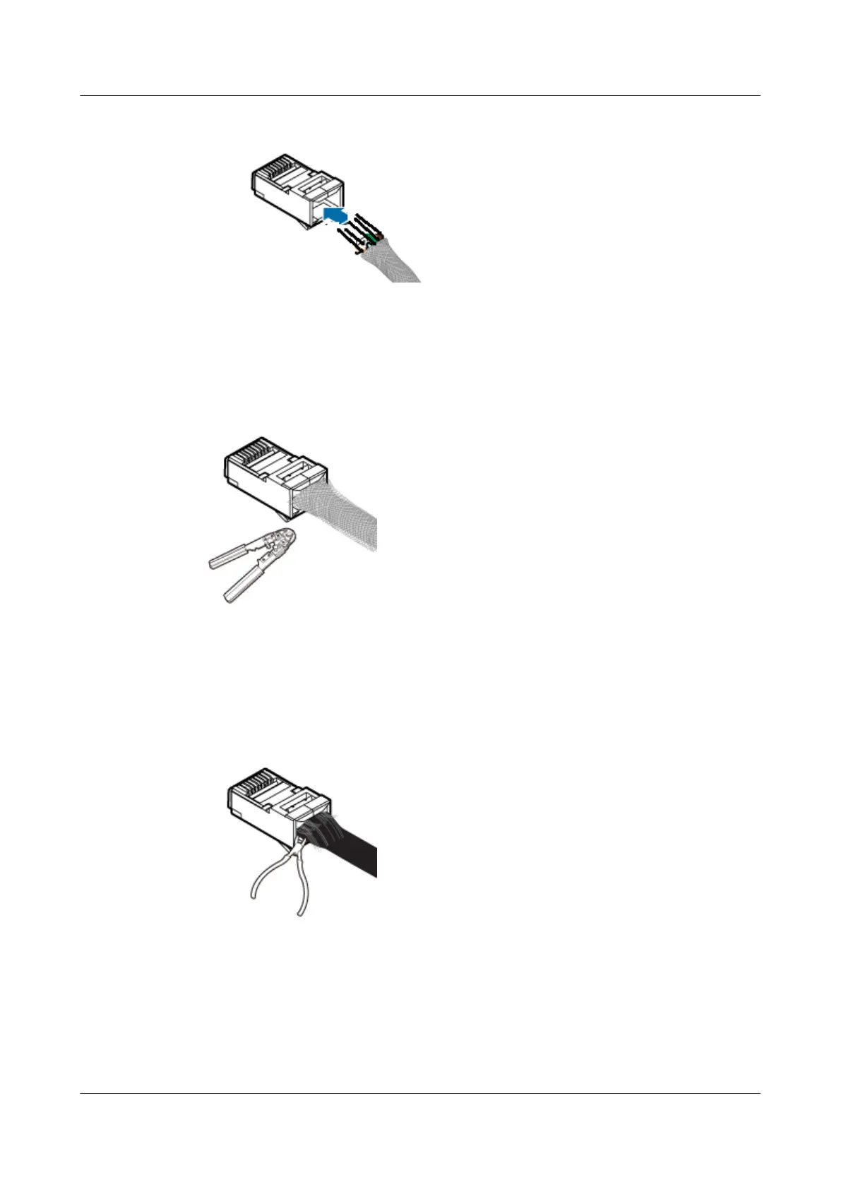
Figure 5-60 Routing core wires through the connector
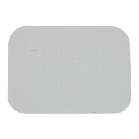
Step 4 Use the crimping tool to crimp the connector, as shown in Figure 5-61.
Figure 5-61 Crimping the connector
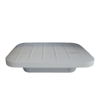
Step 5 Neatly cut braid shields exposed out of the connector along the load bar, as shown in Figure
5-62.
Figure 5-62 Neatly cutting braid shields
Step 6 Repeat Step 1 through Step 5 to assemble the integrated shielded RJ45 connector on the other
end of the network cable.
----End
AP4050DN-E
Hardware Installation and Maintenance Guide
5 Appendix
Issue 05 (2018-02-02) Huawei Proprietary and Confidential
Copyright © Huawei Technologies Co., Ltd.
69