Do you have a question about the Huawei ATN 950B and is the answer not in the manual?
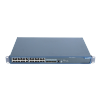
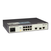
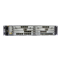
Describes the physical appearance and installation options of the ATN 950B.
Details the slot allocation for boards within the ATN 950B chassis.
Lists supported boards and their valid slot assignments in the ATN 950B.
Explains how boards work together to provide equipment functions.
Presents physical and environmental specifications of the ATN 950B.
Details the DC and AC power supply structures and backup mechanisms.
Describes the PIU board, its functions, and specifications.
Covers the EPS30-4815AF external AC power supply system.
Describes the air flow direction for heat dissipation in the ATN 950B.
Details the AND1FAN, a fan board, including its functions and specifications.
Introduces the CXPA/CXPB board, its role, and housing.
Lists the key functions and features of the CXPA/CXPB board.
Explains the internal modules and signal flow of the CXPA/CXPB board.
Describes the indicators, buttons, and interfaces on the CXPA/CXPB front panel.
Details the CF card and DIP switch functionalities on the CXPA/CXPB.
Provides dimensions, weight, and power consumption of the CXPA/CXPB.
Describes the AND1EM4T board: functions, principle, front panel, specs.
Details the AND1EM8T board: functions, principle, front panel, specs.
Describes the AND1EM4F board: functions, principle, front panel, specs.
Details the AND1EM8F board: functions, principle, front panel, specs.
Describes the AND1EX1 board: functions, principle, front panel, specs.
Details the AND1ML1/ML1A boards: functions, principle, front panel, specs.
Describes the AND3ML1A/ML1B boards: functions, principle, front panel, specs.
Details the AND2MD1A/MD1B boards: functions, principle, front panel, specs.
Explains the function of filler panels for shielding and ventilation.
Describes the appearance and valid slot locations for filler panels.
Covers the appearance and application of eSFP optical modules.
Explains the purpose of optical module labels for identification.
Details power supply and grounding cables for the ATN 950B.
Describes Ethernet cables used for NM signals.
Covers external clock cables and 120-to-75-ohm clock cables.
Lists Ethernet, 75-ohm E1, and 120-ohm E1 service cables.
Describes types of fibers and fiber connectors.
Lists and describes various safety labels on the chassis and boards.
Shows the locations of labels on the ATN 950B chassis.
Lists indicators for different boards of the ATN 950B.
Explains the STAT indicator states and their meanings.
Explains the PROG indicator states and their meanings.
Explains CRIT indicator states and their meanings.
Details technical specs for GE and FE optical interfaces.
Details technical specs for FE and GE electrical interfaces.
Details technical specs for 10GE optical interfaces.
Details technical specs for E1 electrical interfaces.
| Storage Temperature | -40°C to 70°C |
|---|---|
| Relative Humidity | 5% to 95% (non-condensing) |
| MTBF | 200, 000 hours |
| Ports | 4 x 10GE SFP+ |
| Switching Capacity | 240 Gbps |
| Dimensions (H x W x D) | 44 mm x 442 mm x 420 mm |
| Operating Temperature | -40°C to 65°C |